Chapter 4 serial ports – Remote Processing RPC-2350 User Manual
Page 20
CHAPTER 4
SERIAL PORTS
4-1
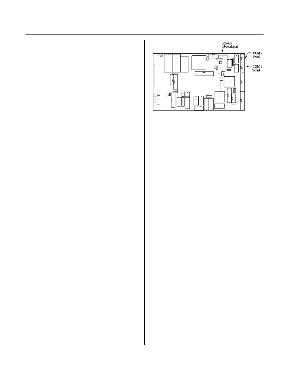
Figure 4-1 Serial por t connector location
CHAPTER SYNOPSIS
SERIAL PORTS CHAPTE R 4
Overview of RPC-2350 serial capabilities
Using RS-422/485
Networking with RS-485
Preven ting program stops (breaks)
SPI port information
DESCRIPTION
The RPC -2350 has two serial ports that can be used for
interfacing to a printer , ter minal, or other ser ial devices.
A SPI p ort is also pr ovided. This chap ter descr ibes their
characteristics and how to use them. F requent
references are m ade to commands listed in the
CAMBA SIC Programming Manual . P lease ref er to this
manual for mor e information.
Serial por ts are num bered C OM 1 and CO M2. COM 1 is
used for program development. It is RS-232 only.
During run time, it can be used for other functions such
as writing to a printer or serial display. COM 2 is a
general purpose serial port. Its outputs can be RS-232,
RS-422, or RS-485 level compatible.
Both ports sup port XO N/ XOF F pr otocol to contr ol data
transmission. Each por t has a 256 character interrupt
driven inp ut and output bu ffer. This allow s charac ters to
be sent out (using PRINT) without slowing down
program execution. Howeve r, if the PRINT buffer fills,
program execution is suspended until the buffer em pties.
Both ports have a 256 character input buffer. When
more than 256 characters have been received, extra ones
are ignored.
The baud rate, parity, data length, stop bits, and com
p o r t t yp e ar e c ha n ge d us in g th e C O NF I G BA U D
command.
COM1 SERIAL PORT
COM 1 is J1 and is called the Console port on the card.
This port uses a VTC-9F serial cable to connect to a PC
and other external serial devices. The cable is wired
one-to-one, with pin 1 on the 10 pin connector lining up
to pin 1 on the D B-9. T he connec tor plugs dir ectly into
a 9 pi n s e ri a l p o r t c o nn e ct or o n a P C .
This port is normally used for program ming. D uring
run tim e it may be u sed as a gene ral pur pose seria l port.
When used for programming or with the INPUT
s ta t em e n t, i t wi ll ac c ep t A S C II c ha r a ct e r v a lu e s f r om 0
to 127. When used with the INKEY$ and COM$
functions, it returns ASCII values from 0 to 255.
No control lines (like CTS or RT S) are available on
COM 1. A pull up resistor is on the CTS output should a
communication program or device require a positive
indication the port is alive.
COM2 SERIAL PORT
COM 2 is an RS-232, RS-422, or RS-485 por t. It also
uses a VTC-9F serial cable to connect to PC’s and other
serial devices. CO M2 is identical to COM1 except that
it has 2 hardware handshaking lines, CT S and RTS.
NOTE: The CT S output line is low on power up or
reset. This is to prevent the RS-485 transmitter
from turning on and adversely affecting network
communication. RS-232 communication may
be affected by holding off the sender from
sending data. You must enable the CT S output
as described below under “ Comm unication flow
control” .
Jumper W 4 determines if COM 2 receive is RS-232 or
RS-422/485.
W4[1-2]
RS-422/485
W4[2-3]
RS-232
Use CO NFIG BAUD to tell the system the type and
characteristics of this port. Default is RS-232, 19, 200
baud, 8 data, 1 stop bit. .