Chapter 4 serial ports – Remote Processing RPC-2350 User Manual
Page 22
CHAPTER 4
SERIAL PORTS
4-3
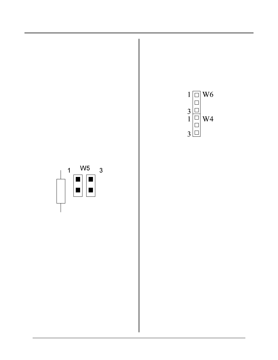
Figure 4-2
RS-485 operates in one of two modes: 2 wir e and 4
wire. ( An extr a wire is actually neede d as signal
reference. ) There are pr o’s and con’s to 2-wire vs 4-
wire systems and they are not discussed here.
Mechanically, to make a 2-wire system, simply connect
T+ to R+ and T- to R- on P3.
When you connect the RPC -2350 to another device, the
T+ ,T-, R+ and R- signal lines may be reversed. That
is, yo u may ne ed to connec t T+ to T- and so on. This
is due to naming convention confusion when RS-485 was
first introduced.
RS-422/485 OPERATING INFORMATION
RS-422/485 Termination network
When the RPC -2350 is the last physical unit on a
network (RS-485), or it is the only unit (RS-422), the
receiver must be terminated to prevent ringing. Insert
jumpers in W5[1-2][3-4] to install the network
terminator. See figure 4-2 below.
Only one slave device on a RS-485 network should have
a terminator installed. The host transmitter shou ld also
have a 100 ohm resistor in series with a 0.1 m fd
capacitor across its T+ and T- terminals. The
term inator on the RPC -2350 include s pull up and pull
down resistors to prevent lines from floating and
generating er roneous char acters.
Two- and four- wire R S-485
The RS-485 port on the RPC -2350 is set up for 2- or 4-
wire mode through jumper W6. This jumper either
always en ables rec eive (W6 [2-3]) or enables it only
when the transmitter is off(W6[1-2]).
W6[1-2]
Receive off while transmitting (2-wire)
W6[2-3]
Receive always on (4-wire mode)
RS-485 Transmitter turn-off
The RS-485 transmitter is automatically turned on and
off by CAM BASIC operating system. You must specify
RS-485 mode in the CON FIG BAU D 2 comm and.
During two wire mode and W6[1-2] is set, the receiver
is turned of f when the transm itter is turne d on. This
keeps the RPC-2350 from receiving what was just sent
out.
NOTE: Do not ope rate RS -485 at 150 ba ud. Autom atic
turn off is not adequate. Contact RP C for sugg estions.
Figur e 4-3 Jum per W 4 & W 6 detail
Two-wire RS-485
Mechanically, to make a 2- wire system, simply connect
T+ to R+ and T- to R -. M ake sure CON FIG BAUD is
set up for RS-485 m ode. Se t jumper W 6[1-2]. T his
prevents data transmitted from getting received.
Network response time considerations
When the last chara cter is sent ou t, an internal tim er is
activated. When the timer is done, the RS-485
transmitter is turned off. The tim er shuts off the
transmitter a bout 1/4 to ½ char acter time after the last
charac ter is sent out. The differ ence is due to sto p bit
and parity requirements and to allow for line settling.
Normally, this is not a problem. However, if a very
high speed sys tem is contr olling the netw ork, it is
possible two transmitters can be on simultaneously,
garbling data. Any responding systems on the network
should wait at least ½ character time before sending a
message packet. W hen using other 2350' s on a network,
this will not be a pr oblem at 1 9200 baud a nd proba bly
will not be one at lower r ates.
Multi-drop Network
You can use the RPC-2350 in a m ulti-drop network by
using CO M2' s RS-422/ 485 port. You can c onnect up to
at least 32 units (including other RPC-2350's) over a
4,000 foot range.
The host transmits data packets to all of the devices, or
nodes, in the network. A data packet includes an