Chapter 8 analog i/o, Analog output – Remote Processing RPC-2350 User Manual
Page 47
CHAPTER 8
ANALOG I/O
8-5
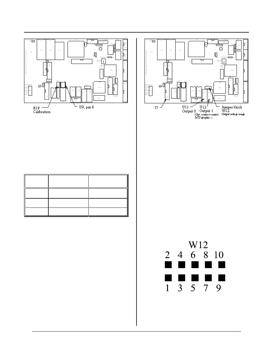
Figure 8-2 Calibr ation
Figure 8-3 Analog output IC’s, jumper, and connector
Figure 8-4 Jumper W12 detail
ANALOG OUTPUT
Two o ptional analog o utput channe ls are indep endently
configured for three voltage ranges. These ranges are
jumpered in hardwar e. Refer to the following table for
jumper settings. See Figu re 8-4 for W12 de tail.
Range
(Volts)
J7-17
(AOT 0)
J7-19
(AOT 1)
0 to + 5
W12[2-4]
W12[1-3]
0 to + 10
W12[8-10]
W12[7-9]
-5 to + 5
W12[6-8]
W12[5-7]
Chann el 0 output is J7, pin 17 and cha nnel 1 is J7, pin
19.
Analog output 1 may optionally be used for software
contrast adjustment for the LCD graphics display. When
it is used for this purpose, analog output 1 may not be
used for o ther pur poses, including 4-20 M a output.
IC Installation
The figure below shows wher e D/A IC’s are installed.
Analog output IC’s are Analog Devices AD7248 type.
This part may be ordered under Remote Processing Part
number 1454.
Follow these steps to install analog output IC ’s.
1.
Turn off power to the board.
2.
Orien t board as shown ab ove. Orient IC so pin
1 (notch on IC) is towards the top of the board.
3.
Install IC into appropriate socket. U11 for
channel 0, U12 for channel 1.
4.
Set jumper W12 for desired output voltage.
You are now r eady to power up the board.
Programming voltage output
The AOT command is used to send data to an analog
output. T he syntax is:
AOT channel, value
Where:
channel specifies the an alog channe l to write da ta to