2 standard menu, 7commissioning, 4 leds and keys – Pilz PMCprimo DriveP.01/AA0/4/0/0/208-480VAC User Manual
Page 184
7.4
LEDs and keys
7
Commissioning
Pilz GmbH & Co. KG, Felix-Wankel-Straße 2, 73760 Ostfildern, Germany
Telephone: +49 711 3409-0, Telefax: +49 711 3409-133, E-Mail: [email protected]
7-12
7.4.2
Standard menu
Standard menu
7-
][Inbetrieb_Menu_Standard
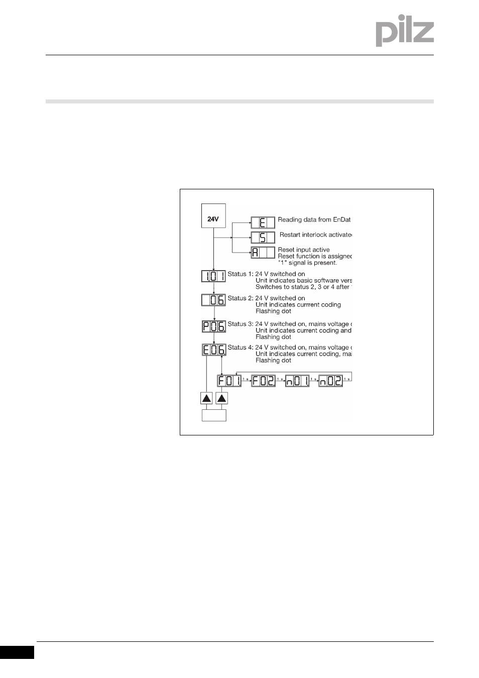
Once the servo amplifier is switched on you will have access to the sta-
tus, error and warning messages via the standard menu.
The diagram below shows how the display is structured.
Fig. 7-3:
Standard menu display
Reading data from EnDat
Restart interlock activated
Reset input active
Reset function is assigned to an input.
"1" signal is present.
Status 1: 24 V switched on
Unit indicates basic software version
Switches to status 2, 3 or 4 after 1 s
Status 2: 24 V switched on
Unit indicates currrent coding
Flashing dot
Status 3: 24 V switched on, mains voltage on
Unit indicates current coding and mains voltage on
Flashing dot
Status 4: 24 V switched on, mains voltage on, enable
Unit indicates current coding, mains voltage on, enable
Flashing dot
Error/warning messages: all errors or warnings
that occur are displayed in succession for
4 flash cycles
Parameter
Power on
- PMCprimo DriveP.01/AA0/5/0/0/208-480VAC PMCprimo DriveP.12/AA0/4/0/0/208-480VAC PMCprimo DriveP.12/AA0/4/P/0/208-480VAC PMCprimo DriveP.03/AA0/4/0/0/208-480VAC PMCprimo DriveP.06/AA0/4/0/0/208-480VAC PMCprimo DriveP.24/ABB/4/0/0/208-480VAC PMCprimo DriveP.03/AB0/5/0/0/208-480VAC PMCprimo DriveP.06/AB0/2/0/0/208-480VAC PMCprimo DriveP.03/AB0/3/0/0/208-480VAC PMCprimo DriveP.06/AB0/3/0/0/208-480VAC PMCprimo DriveP.12/AB0/2/0/0/208-480VAC PMCprimo DriveP.12/ABC/4/P/0/208-480VAC PMCprimo DriveP.12/AB0/3/0/0/208-480VAC PMCprimo DriveP.03/AB0/2/0/0/208-480VAC PMCprimo DriveP.12/AAC/4/0/0/208-480VAC PMCprimo DriveP.24/AA0/5/0/0/208-480VAC PMCprimo DriveP.12/AA0/2/0/0/208-480VAC PMCprotego D.01/000/0/0/2/208-480VAC PMCprotego D.03/000/0/0/2/208-480VAC PMCprotego D.06/000/0/0/2/208-480VAC PMCprotego D.12/000/0/0/2/208-480VAC PMCprotego D.24/000/0/0/2/208-480VAC PMCprotego D.12/000/0/P/2/208-480VAC PMCprotego D.24/000/0/P/2/208-480VAC PMCprotego D.01/200/0/0/2/208-480VAC PMCprotego D.01/100/0/0/2/208-480VAC PMCprotego D.01/010/0/0/2/208-480VAC PMCprotego D.06/010/0/0/2/208-480VAC PMCprotego D.06/100/0/0/2/208-480VAC PMCprotego D.06/200/0/0/2/208-480VAC PMCprotego D.03/010/0/0/2/208-480VAC PMCprotego D.03/200/0/0/2/208-480VAC PMCprotego D.03/100/0/0/2/208-480VAC PMCprotego D.12/010/0/0/2/208-480VAC PMCprotego D.24/200/0/P/2/208-480VAC PMCprotego D.12/200/0/0/2/208-480VAC PMCprotego D.12/100/0/0/2/208-480VAC PMCprotego D.12/010/0/P/2/208-480VAC PMCprotego D.12/200/0/P/2/208-480VAC PMCprotego D.24/100/0/P/2/208-480VAC PMCprotego D.24/010/0/P/2/208-480VAC PMCprotego D.12/100/0/P/2/208-480VAC PMCprotego D.24/200/0/0/2/208-480VAC PMCprotego D.24/100/0/0/2/208-480VAC PMCprotego D.24/010/0/0/2/208-480VAC