1 adding and deleting sources, 7 line arrays, 1 array settings – d&b TI 385 d&b Line array design User Manual
Page 20
Name: Each listening plane in ArrayCalc requires a
unique name.
Position center: This is where you start to measure the
venue. Specify the height (z) of your measuring instrument
above ground.
Lower edge: Measure the angle and distance to the
lower edge of the tier you want to capture at 0°, up to mid
point and at 90°.
Upper edge: Measure the angle and distance to the
upper edge of the tier you want to capture at 0°, up to mid
point and at 90°.
Position off center: Now move your measuring
instrument to a position off center on the x-axis in direction
of 0°. Specify the coordinates of your instrument including
height (z) above ground. This second measuring position is
essential to determine the curvature of the arena.
Measure up to the specified mid points on the lower and
upper edges of the tier you want to capture.
Segments/Create
planes:
After
entering
all
measurements, specify the number of segments into which
the resulting superelliptic listening plane should be split and
click Create planes.
When you click Create planes, up to 4 new listening planes
will be added to the Venue editor depending on the desired
number of segments you specified. You can edit each
segment separately after selecting it.
Top view and Profile view diagrams
The Top view diagram displays the venue and the listening
planes added to the project. The planes can be modified in
the diagram in x (depth) and y (width) directions using the
mouse.
The Profile view diagram also displays the listening planes
added to the project. Here the planes can be modified in z
direction (height) using the mouse.
In both diagrams, a number of tool buttons are provided to
modify the venue:
Zoom in/out (
):
Zooms into or out of the venue. Please note that double-
clicking the diagram always sets the zoom factor to such a
value that all listening planes and obstacles are displayed.
Duplicate (
):
Creates a new listening plane or obstacle as a duplicate of
the one currently selected.
Mirroring (
):
Creates a new listening plane or obstacle as a duplicate of
the one currently selected and mirrors its position either at
the xz or at the yz plane.
Undo / redo (
):
Undoes or redoes the last action. The Venue editor in
ArrayCalc V7.x.x supports 7 undo / redo steps.
Delete (
):
Deletes the currently selected listening plane or obstacle
from the venue.
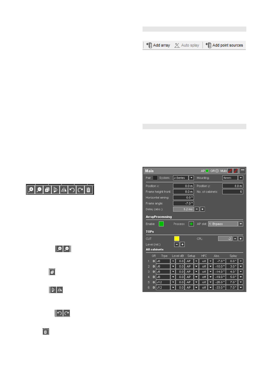
10.6 Sources page
10.6.1 Adding and deleting sources
You can create up to 14 individual arrays or symmetrical
pairs of arrays and in addition 14 groups of point sources
by clicking the "Add array" or the "Add point sources"
button in the toolbar or by selecting the "Add array"/"Add
point sources" item from the Sources menu. For each line
array or point source group in the project, a separate
settings dialog is created and available for use.
You can delete the sources open for editing by clicking the
"Delete" button in the toolbar or by selecting the "Delete"
item from the Sources menu. This action has to be confirmed
and can be canceled again before final execution.
10.7 Line Arrays
10.7.1 Array settings
The following description and examples refer to a line array
dialog in ArrayCalc with V-Series cabinets selected. J, Y, Q
and T-Series system design is performed in the same way.
Differing procedures for xA-Series arrays are described
when applicable.
TI 385 (6.0 EN) d&b Line array design, ArrayCalc V8.x
Page 20 of 54