4 mechanical load conditions for arrays – d&b TI 385 d&b Line array design User Manual
Page 24
10.7.4 Mechanical load conditions for arrays
WARNING!
P
otential risk of personal injury and/or
damage to materials.
Never set up an array which exceeds the load limits.
— Reduce the number of cabinets or the total splay angle
until the load conditions are within limits.
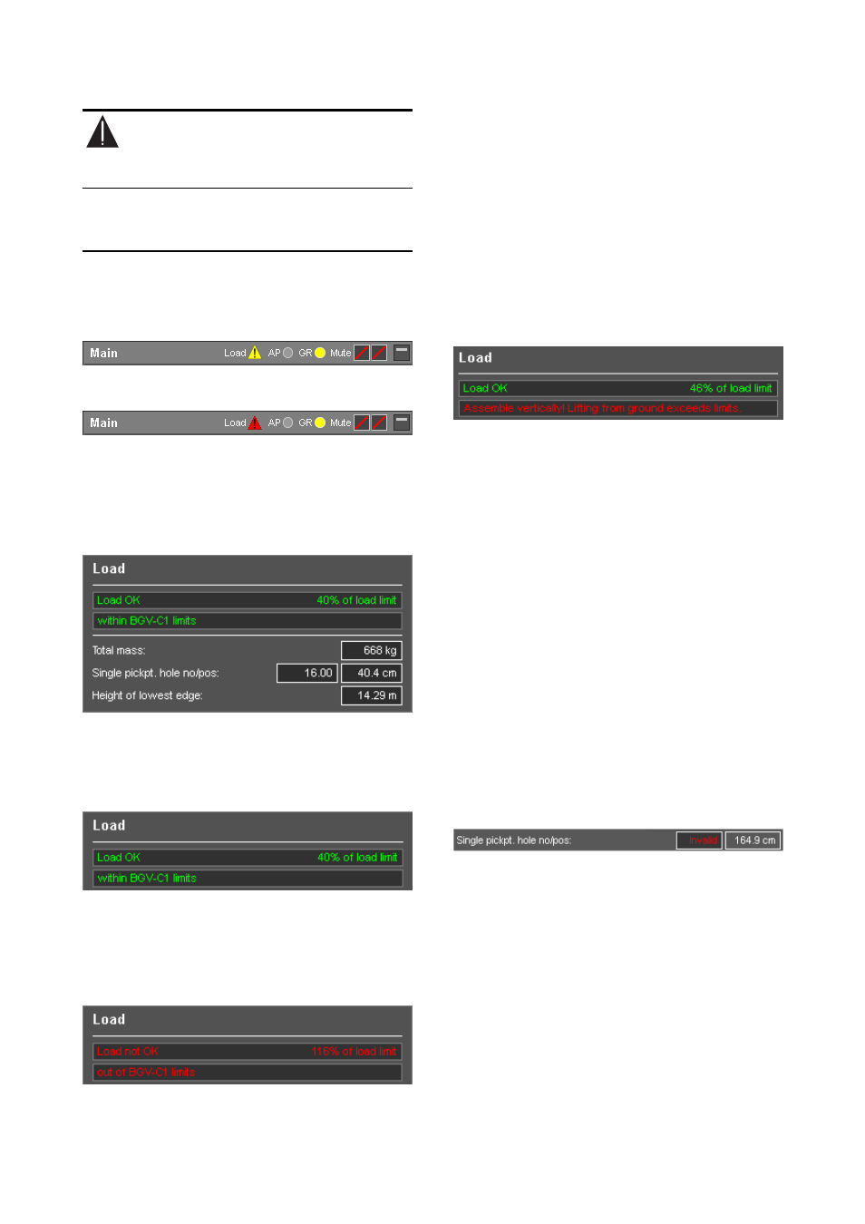
When a given array configuration exceeds the mechanical
load limits, a warning is displayed in the array´s headline:
Exceeding the BGV-C1 limits will bring up a yellow warning
symbol:
Exceeding the absolute load limits will bring up a red
warning symbol:
Array selection
You can select any array defined in the project for display
and simulation by opening the respective array settings
dialog.
Load conditions for selected array
Load conditions and single pick point settings
This section provides general information on the mechanical
load conditions of the array:
If the load conditions are within the load limits, the following
message will be displayed:
For applications covered by the BGV C1 Rule for the
Prevention of Accidents, "within BGV-C1 limits" is displayed
as additional information if the designed array fulfills the
load requirements.
If the load limits are exceeded, the following message will
be displayed:
For applications covered by the BGV C1 Rule for the
Prevention of Accidents, "out off BGV-C1 limits" is displayed
as additional information if the designed array exceeds the
load requirements.
Load conditions for xA-Series arrays
Since xA-Series arrays are intended for fixed installation use
only, the additional requirements of the BGV C1 rules do
not apply. Consequently, no further details are provided
here.
Some xA-Series configurations would exceed the rigging
system load capacity if the fully assembled array was lifted
from horizontal assembly position (i.e. when the array was
assembled on the floor):
In this case, the array must be assembled vertically. Add
only one cabinet to the suspended array at a time.
Total mass
The calculated weight of the array including all rigging
components.
Single pickpt. hole no/pos
For single hoist operation, these values indicate where the
Load adapter should be attached to the Flying frame to get
the desired vertical aiming of the array.
The closest hole of the frame's hole grid, counted from the
front of the frame, as well as the exact position as a
distance from the front of the frame's center beam are
displayed.
The J, V and Y Load adapters supplied with the J, V and Y
Flying frames allow the pick point position to be set with a
resolution of a 1/2 hole. The Q and T-Series Flying frames
with Q/T Load adapter provide a resolution of 1/4 hole.
If the calculated pick point is beyond the frame, an error
message will be displayed:
Single hoist operation might not be allowed for large
arrays. In this case these cells show "--".
Height of lowest edge
Height above the ground of the lowest edge of the array.
Allows easy verification of trim height using a laser range
finder or a tape measure.
TI 385 (6.0 EN) d&b Line array design, ArrayCalc V8.x
Page 24 of 54