2 auto splay, 3 copy, paste, paste as new – d&b TI 385 d&b Line array design User Manual
Page 23
Usually the distances to the audience that an array has to
cover decrease from the top to the bottom of a column,
consequently it is desirable to gradually increase the
vertical splay angles between adjacent cabinets, resulting in
a spiral -or "J"-shape.
If a desired level distribution cannot be achieved with a
given number of cabinets and/or external restrictions in the
placement of the array, the levels of individual cabinets can
be modified. This should always be the last option, and
generally be limited to a few dBs.
Line / Arc selection
For J, V, Y, Q and T-Series loudspeakers the d&b amplifiers
provide two different configurations each and they are set
depending on the mechanical design of the array.
The Arc (Q1: standard) configuration is applied when the
speakers are used in curved array sections while the Line
configurations are used for groups of four or more
loudspeakers when coupled to form a long throw array
section.
Compared to the Arc (Q1: standard) configuration the Line
setting uses different CPL attenuation functions reducing the
upper midrange to compensate for the extended near field
effect of the straight array section.
With more than two consecutive splay settings of 0° or 1°
(V, Y, Q1 and T10: 0°, 1° or 2°; 10AL(-D): 0°, 1°, 2° or
4°), the Line setting should be used for the respective
cabinets. All the other cabinets should be operated using
the Arc (Q1: standard) configuration.
The transition from Line to Arc/standard configuration within
the array is made according to the splay progression but
certain deviations may be permitted due to the grouped
wiring of the cabinets.
HFC settings
Available for all line array speakers. Increases high
frequency respo
nse to compensate for air absorption
effects. HFC can only be set when the "air absorption"
switch is activated.
Note: Splay angles have to be set before activating
ArrayProcessing. When ArrayProcessing is enabled, the
individual cabinet settings can no longer be modified,
i.e. all parameters in the table like Level, Line/Arc, HFC
are disabled.
10.7.2 Auto Splay
For line array design you may use the "Auto splay" function
located in the tool bar (or in the Sources menu) to get start
values which should later be optimized manually to achieve
the desired SPL distribution.
The algorithm's first criterion attempts to fully cover the
activated listening planes. If more total splay is available
than needed for coverage, a progressively splayed array
with cabinet aiming points equally spaced along the
listening planes is created. The Flying frame angle (= top
cabinet) will be aimed at the farthest listening point.
If the Auto Splay function proposes a set of large splay
angles, only slightly increasing from top to bottom, this is a
good indication that more cabinets should be considered
for the application.
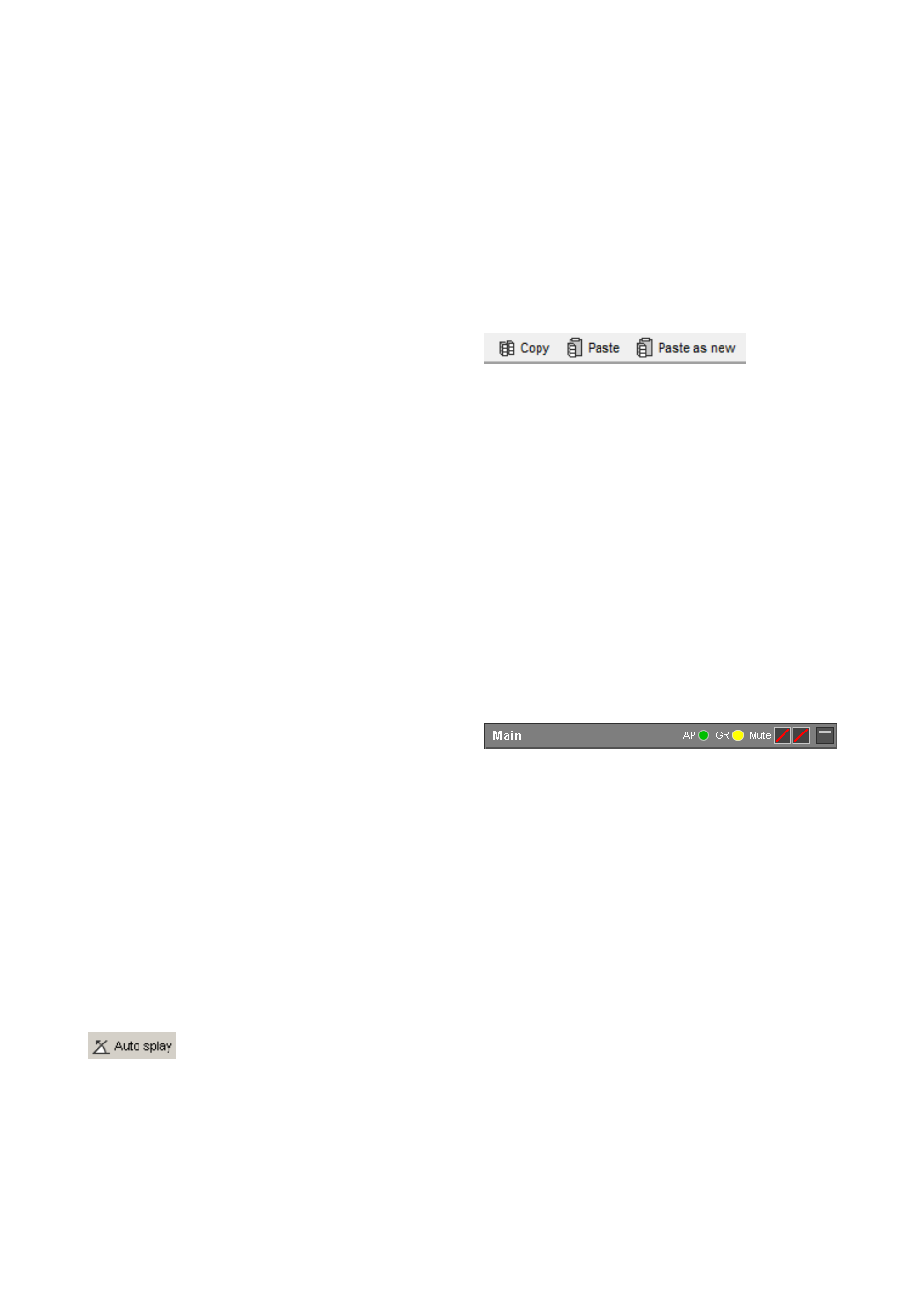
10.7.3 Copy, Paste, Paste as new
— Copy: Creates a copy of the selected array or groups
of sources with all settings in the internal clipboard.
— Paste: Pastes all source settings copied to the internal
clipboard into the selected array or group of sources.
— Paste as new: Creates a new array or group of
sources containing all settings from the internal
clipboard.
Export/import of array settings
You can export defined array settings to an ArrayCalc
description file (*.dbea). This file including the exported
array settings can then be imported in other projects or in
the same project again, for example for comparative
purposes. To use the array export/import function, right-click
in the Array dialog to activate the context menu or select
'Export source/Import source' from the Sources menu.
Gain Reduction indicator GR
Each cabinet has a yellow GR LED which indicates when a
particular amplifier channel has reached its limit for the
given signal level with one of the simulated input signals
selected for the 2D and 3D SPL plots.
A possible Gain Reduction is not considered in the SPL
calculations, i.e. will not limit a cabinet´s calculated output
and will therefore not modify the SPL distribution.
Consequently, with (too) many GR LEDs on, the calculated
and displayed level distribution might actually not be
attainable.
Whenever a GR LED lights up for a cabinet within an array,
the GR LED in the headline is activated even if the array is
not opened for editing.
TI 385 (6.0 EN) d&b Line array design, ArrayCalc V8.x
Page 23 of 54