d&b TI 385 d&b Line array design User Manual
Page 22
Process:
Opens the ArrayProcessing dialog where the target level
distribution can be defined and the related ArrayProcessing
data can be calculated. Up to ten configurations can be
stored to the individual AP slots. For details see 11.4
ArrayProcessing dialog on page 51.
AP slot:
Selects the ArrayProcessing slot that is used to calculate the
diagrams. Set to “Bypass” when ArrayProcessing is
disabled.
Array group controls
Depending on the selected array and the cabinet types
used, group controls are available which define the main
amplifier settings for the whole array or functional parts of
it. The simulation result changes in accordance with the
settings.
General group controls
Mute: Located in the headline in order to be available
even if the array is not opened for editing. Depending on
the setting of the Mute switch, an array will be taken into
account in the 3D mapping and be displayed, or not
displayed, on the Alignment page.
The Level vs. distance result of the individual array is not
affected by the Mute setting.
Delay value for the array: Acts as an absolute
control, i.e. the value entered here will be set for each
loudspeaker of the array.
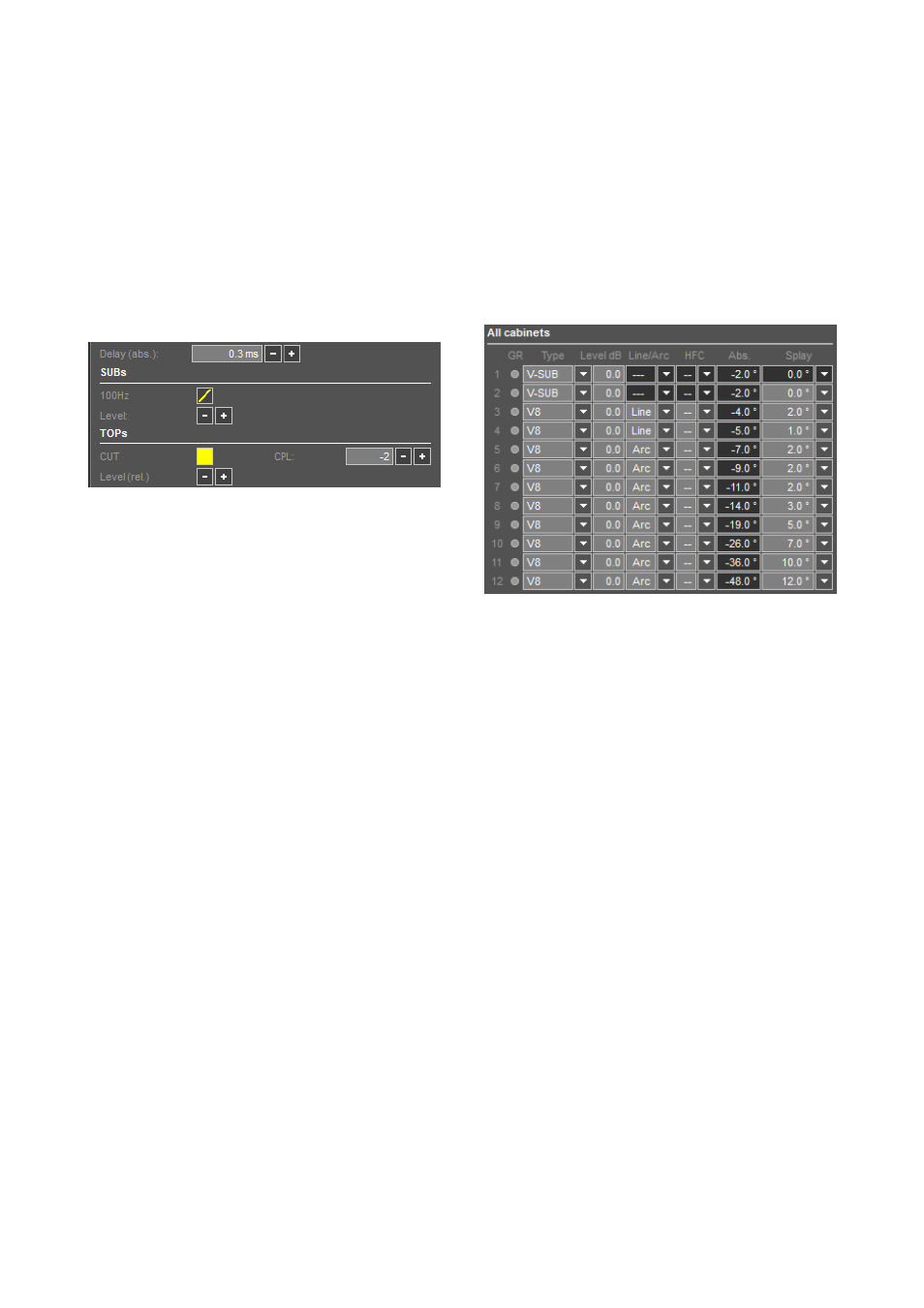
Loudspeaker specific amplifier controls
Level (rel.): Independent level controls for SUBs and
TOPs each working with relative values to maintain
individual level tunings in the table below.
Note: When ArrayProcessing is enabled, all elements
of the array are set to identical levels. T
he Level
controls for SUBs and TOPs apply to all cabinets, no
matter which control is used.
CUT: Available for all line array TOP speakers. Set to CUT,
the low frequency level is reduced. The source is now
configured for use with the system´s dedicated subwoofers.
The CUT circuit must be set consistently within a source.
CPL: Available for all line array speakers. Reduces the low
and mid frequency level. The setting depends on the array
length and curvature.
HCD: Available for active cardioid J-SUB and J-INFRA
subwoofers. Changes from cardioid to hypercardioid mode.
INFRA, 100 Hz, 70 Hz: Subwoofer crossover options
for different models.
Note: CUT, INFRA, 100 Hz/70 Hz have to be set
before enabling ArrayProcessing. The HCD function is
no longer available with ArrayProcessing enabled.
Line array configuration settings, Levels and
Splay angles
You can define the amplifier settings for each cabinet
individually. However, if two or more cabinets are linked to
the same amplifier or amplifier channels, identical settings
have to be chosen for these cabinets.
The coverage and level distribution in the audience areas
are mainly adjusted using the splay angles between the
cabinets.
The first entry in the column is the angle between the Flying
frame and the first cabinet which is always set to 0°. Left to
the splay column the absolute vertical aiming of each
cabinet is indicated.
The J8/J12 wavefront characteristic allows a maximum
splay angle between adjacent cabinets of 7° while still
providing a gapless coverage at high frequencies
(V8/V12: 14°; Y8/Y12: 14°; Q1: 14°; T10: 15°).
Lower frequencies will disperse into a wider area creating
an overlap of the coverage patterns between the single
cabinets. Therefore directivity and the level of lower
frequencies increases with every cabinet added to the
column.
Decreasing the splay angles will enforce the overlap of the
coverage patterns at high frequencies resulting in increased
directivity and high-frequency output.
Small splay angles are used when covering remote
audience areas where additional high-frequency energy is
needed to maintain intelligibility in a reverberant venue,
and to compensate for the HF absorption of air which
increases with distance.
TI 385 (6.0 EN) d&b Line array design, ArrayCalc V8.x
Page 22 of 54