18 cpl circuit – d&b TI 385 d&b Line array design User Manual
Page 45
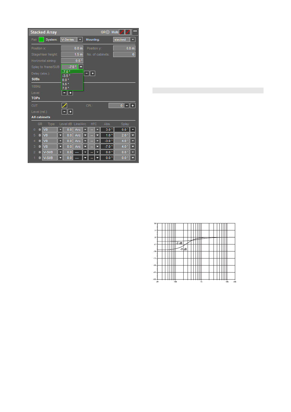
Splay setting of the lowest cabinet
J and V-Series arrays are always mounted on their
appropriate Flying frames. The angle options for the lowest
cabinet are –3°/0°/+3° for J-Series and
–7°/–3.5°/0°/+3.5°/+7° for V-Series and are set in the
"
Splay to frame/SUB" cell.
ArrayCalc assumes the use of a standard flying frame
between SUBs and TOPs. If you use other accessories (e.g.
Z5386 V Stack adapter), please consider the actual
number of splay angles available. In this case, the
difference in height must be compensated by modifying the
"stage/riser height" accordingly.
With Q1 and T10 arrays the splay value below cabinet
no.1 represents the setting according to the scale on the
splay link / cabinet.
When Q Tops are stacked on the Q Flying frame, a value
of 8° results in the cabinet aiming horizontally ("0 to
frame"). However, when stacked on a Q-SUB cabinet the
actual splay angle between these cabinets has an offset of
6°. The setup is best adjusted while watching the absolute
angles of the Q1 cabinets.
When T10 arrays are stacked on a T-Series Flying frame,
the splay angle of the lowest cabinet can only be set to –
2° or 0°.
When T10 arrays are stacked on a T-SUB cabinet, the
splay angle of the lowest cabinet can be set to –2°, –1°,
0°, +1°, +2°, +3°, +4° or +6°.
When T10 arrays are stacked on a T-Series base plate, the
splay angle of the lowest cabinet can range from –8° to
+5° (1° increments).
When Y8/Y12 arrays are stacked on a Y-Series base plate,
the splay angle of the lowest cabinet can range from –7°
to +7°.
With ground stacked systems the low/mid SPL curve
generally shows an increase at the very front when
approaching the stack. Creating a similar curve for the
high/mid frequencies is not advised as to achieve this the
cabinets would have to be placed at the level of the
listeners' ears. This would create dangerous sound pressure
levels at the front, and would not reach the audience at the
rear.
10.18 CPL circuit
The CPL (Coupling) circuit compensates for coupling effects
between the cabinets by reducing the low and mid
frequency level.
You can activate the CPL function using the CPL group
control in the array / point source settings dialog.
J, V- and Y-Series
The CPL function should be applied when J , V or Y-TOP
cabinets are used in arrays of six (J) or four (V, Y) or more
cabinets. As coupling effects change with the length and
curvature of the array, the CPL function differs between Arc
and Line setup. Its design enables (and requires) a common
setting of dB attenuation values between 0 and –9 dB to
be applied to the entire array. CPL begins gradually below
2 kHz, with the maximum attenuation below 100 Hz. At
higher attenuation values the corner frequency of the filter
shifts towards lower values.
The principal function of the CPL circuit for J-Series cabinets
is shown in the diagram below. Please note that all cabinets
within a column must be operated at the same CPL setting.
Frequency response correction of the J-Series
CPL circuit
Q, T and xA-Series
The Q, T and xA-Series CPL circuits work in a similar way,
however the filter corner frequency shifts differently
according to the attenuation to comply with the different
system dimensions and curving possibilities. CPL can be set
between +5 and –9 dB.
Positive CPL values (not supported by ArrayCalc) produce a
low frequency boost.
TI 385 (6.0 EN) d&b Line array design, ArrayCalc V8.x
Page 45 of 54