1 y-sub ground stacks, 2 y-subs flown on top of a y8/y12 array, 3 flown y-sub columns – d&b TI 385 d&b Line array design User Manual
Page 9: 4 y-sub horizontal sub array, 3 v-, y-, j-sub/j-infra subwoofer setup, 1 combined j-, y-sub ground stacks, 2 flown y-, j-subs or j-infra ground stacks, 3 flown y-subs, j-infra sub array
4.2.1 Y-SUB ground stacks
Using Y-SUB cabinets in L/R ground stacks provides
maximum system efficiency due to the ground coupling of
the cabinets.
4.2.2 Y-SUBs flown on top of a Y8/Y12 array
Flown Y-SUBs create a more even level distribution over
distance. Compared to a ground stacked setup the area at
the very front below the arrays has much less low frequency
level because of the longer distance to the subwoofers.
However, when a high level of low frequency energy at the
front is desired, e.g. to compensate for a loud stage level,
additional ground stacked subwoofers may be necessary.
4.2.3 Flown Y-SUB columns
When complete columns of Y-SUBs are flown, the increased
vertical directivity adds to the distance effect described
above and thus creates a longer throw of low frequencies.
Clever positioning of flown subwoofer columns behind the
main and outfill arrays of TOP loudspeakers can greatly
enhance both visual appearance and acoustic performance
of the complete system through increased overall coherence
between the different parts of the system.
4.2.4 Y-SUB horizontal SUB array
Arranging Y-SUBs in a horizontal array (SUB array)
provides the most even horizontal coverage eliminating the
cancellation zones to the left and right of the center of a
typical L/R setup. Refer to section 10.10 on page 32.
4.3 V-, Y-, J-SUB/J-INFRA subwoofer setup
Y-SUB and V-SUB cabinets can be combined in virtually
any application that does not require mechanical
compatibility. Their modes should always be synchronized
(i.e. both in 100 Hz mode or both in standard mode).
When used with J-SUB and J-INFRA cabinets, Y-SUB
subwoofers are always operated in standard mode (i.e.
100 Hz not selected).
Depending on the application and the space requirements
a combination of Y-SUB and J-SUB / J-INFRA cabinets can
be set up in several different ways.
4.3.1 Combined J-, Y-SUB ground stacks
Maximum coupling and coherence of the systems are
achieved when J-SUB and Y-SUB systems are stacked close
to each other. However, make sure to keep a minimum
distance of 60 cm (2 ft) between adjacent stacks. J-SUB
cabinets should be operated in standard mode.
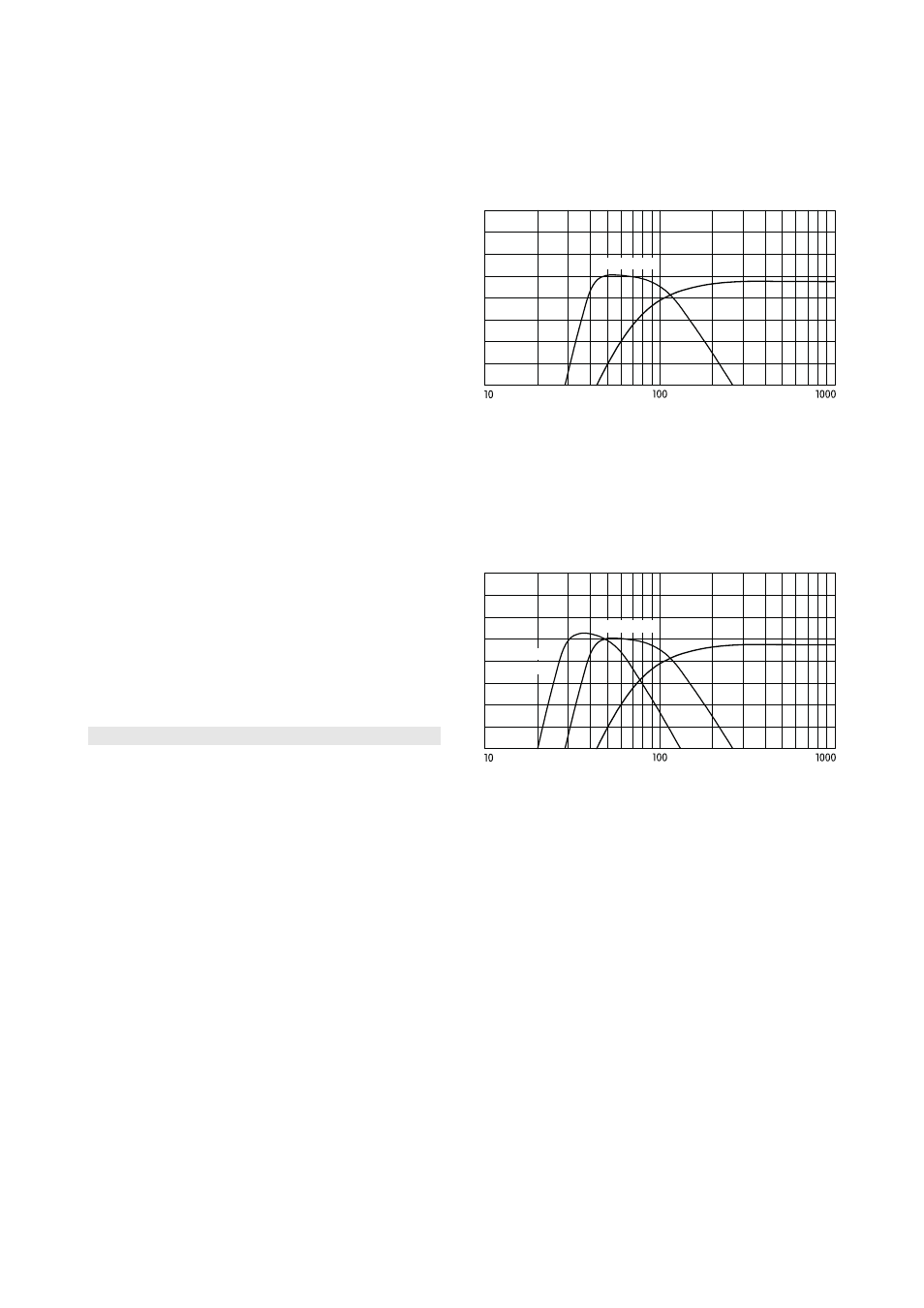
Y-SUB STD
Y8 CUT
Y8 / Y-SUB / J-SUB crossover setup
4.3.2 Flown Y-, J-SUBs or J-INFRA ground stacks
Flown columns of Y-SUBs provide a higher vertical
directivity and thus a longer throw. Ground stacked J-SUBs
or J-INFRA can be operated in either crossover mode
depending on the ratio of flown to ground stacked
subwoofers.
Y-SUB STD
Y8 CUT
J-INFRA
STD
Y8 / Y-SUB / J-INFRA crossover setup
4.3.3 Flown Y-SUBs, J-INFRA SUB array
As an option J-INFRA cabinets can be set up in a horizontal
SUB array in front of the stage. In this case the 70 Hz
setting on the J-INFRA controllers is advantageous. The
correct alignment of the array dispersion and delay settings
is performed using ArrayCalc. Refer to section 10.10 on
page 32.
TI 385 (6.0 EN) d&b Line array design, ArrayCalc V8.x
Page 9 of 54