3 design criteria, 4 physical placement of cabinets – d&b TI 385 d&b Line array design User Manual
Page 33
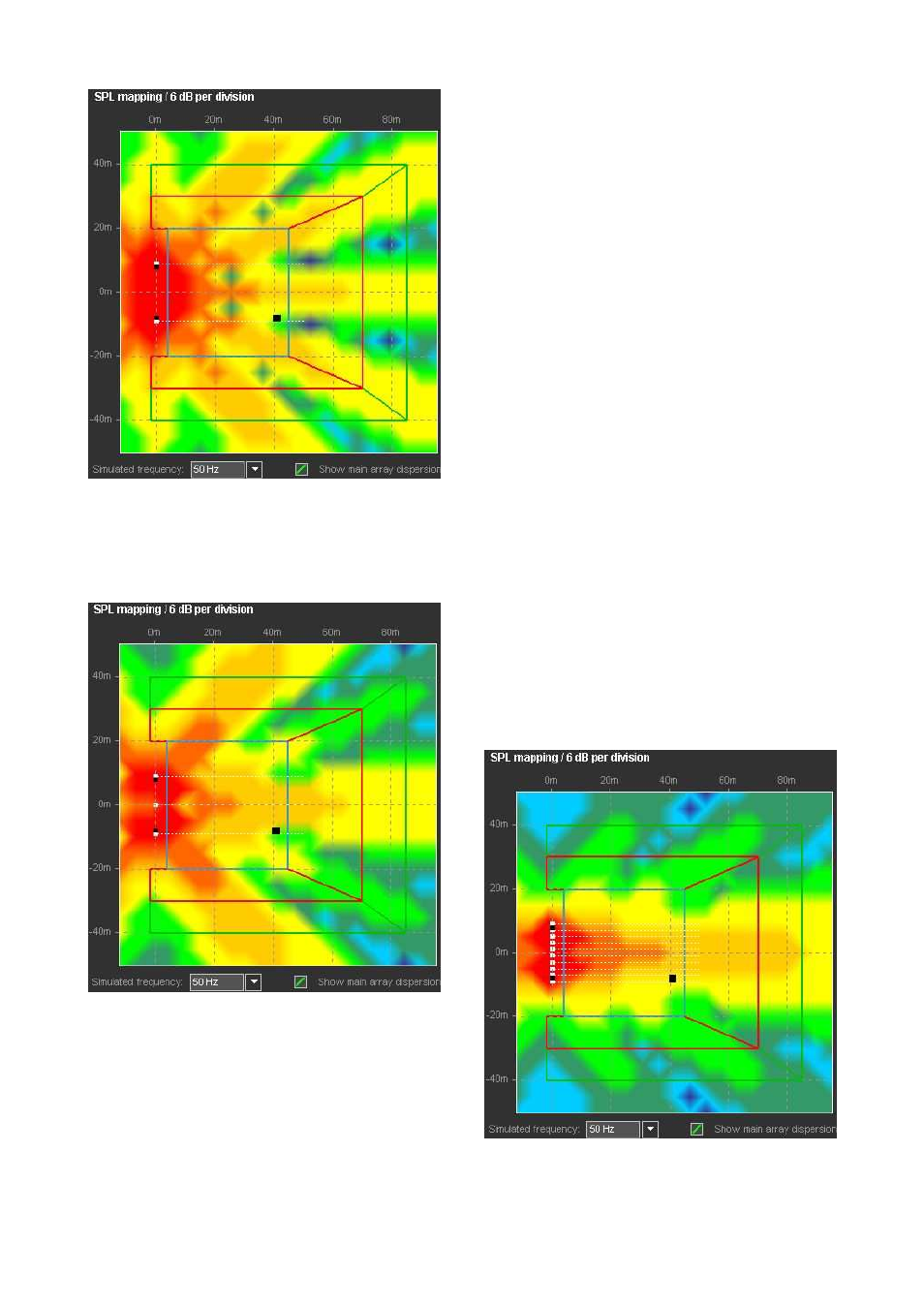
50 Hz mapping L/R subwoofer setup
A common approach to change this behavior is to add an
additional center source. A look at the SPL mapping of a L/
C/R subwoofer arrangement at 50 Hz shows: The zone in
the center of the audience area is more even, but from the
second cancellation zone, it isn't any better.
50 Hz mapping L/C/R subwoofer setup
10.10.3 Design criteria
Two sources, which are spaced at a distance of half the
wavelength of the frequency they reproduce, cancel each
other out in the direction of their connecting line. For
frequencies higher than this, the cancellation axis turns more
and more towards the center axis while a second maximum
appears and increases in level with rising frequency.
In the L/R example above, where the distance from left to
right is 18 m (59 ft) (which is more than 2.5 times the
wavelength at 50 Hz), the main lobe is in the center, there
are 2 side lobes with cancellation zones in between and
beyond, and the third side lobe is just about to appear
clearly.
Consequently, to have full control over the array behavior
within the entire operating bandwidth of the subwoofers,
the source spacing must be close enough to fulfill the half-
wavelength criteria mentioned above for the highest
frequencies at which the subwoofers operate. In the actual
application, the criteria can be undermined slightly: Firstly,
because a subwoofer cabinet is not a theoretical point
source, but has a certain extension, so the spacing between
cabinet centers can be slightly wider than exactly half the
wavelength; secondly, when directional (cardioid)
subwoofers are used, they already have a certain rejection
towards the sides, so the unwanted side lobes are
suppressed to a certain degree.
10.10.4 Physical placement of cabinets
The first step is to array multiple omnidirectional subwoofers
(e.g. Q-SUBs) in a line, close enough to avoid lobing. This is
quite common practice. A look at the 50 Hz distribution of
an array of 10 subwoofers, equally spaced along 18 m
(59 ft), shows a strong center lobe that drops quickly by
more than 12 dB towards the sides of the audience area.
50 Hz mapping of a straight array of 10 subwoofers
TI 385 (6.0 EN) d&b Line array design, ArrayCalc V8.x
Page 33 of 54