1 create r1 files, 2 patches, 3 patch dialog – d&b TI 385 d&b Line array design User Manual
Page 42
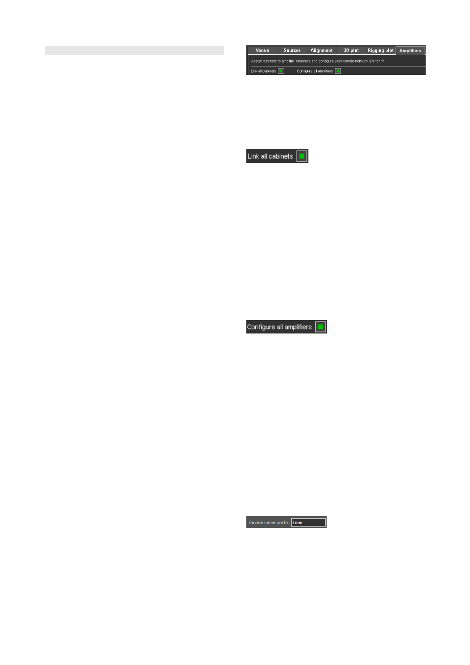
10.13 Amplifiers page
The Amplifiers page of ArrayCalc provides a fast and
convenient way to configure the amplifiers and the patch of
the simulated system. The Amplifiers page also includes an
option for printing out a patch plan.
When saving the ArrayCalc project, all relevant information
for the R1 Remote control project such as amplifiers, groups
and control elements is saved to the same file. To operate
the simulated ArrayCalc project in R1, just open the
respective file using R1.
10.13.1 Create R1 files
In addition to the R1 V2 project file, a Snapshot containing
all settings for the devices and group controls is created.
You can load this Snapshot in R1 V2 by clicking the
appropriate button on the Overview page of the generated
R1 V2 project.
To maintain integrity between an R1 V2 project file and the
Snapshot, the Snapshot is saved within the generated
project file.
Standard procedure
To make effective use of the Amplifiers page, proceed as
follows:
1. Use the Link all cabinets function at the top of the
Amplifiers page.
If necessary, adapt the patch of individual devices
manually. A detailed description is given in section
10.13.3 Patch dialog on page 42.
2. Use the Configure all amplifiers function at the top of
the Amplifiers page.
If necessary, adapt the configuration of individual
devices manually. A detailed description is given in
section 10.13.4 Cabinets section on page 43.
3. Simply save the ArrayCalc project.
4. Open the ArrayCalc project file (*dbac2) in R1 V2.
5. Load the Snapshot using the appropriate button on the
Overview page of the exported R1 project.
Patch plan printout
ArrayCalc provides you with a detailed patch plan printout
including the chosen input type and source. On the
Amplifiers page, select 'Print' from the File menu or press
Ctrl+P (CMD+P for Mac OS X systems).
Patch plan CSV export
ArrayCalc provides you with a detailed patch plan export
to a CSV (comma seperated value) file (*.csv) including the
chosen input type and source. On the Amplifiers page,
open the File menu and select Export/CSV.
10.13.2 Patches
The Amplifiers page provides a patch dialog for each array
in the project to allow individual assignment (patch) of the
cabinets to the respective amplifier channels. Additionally
the dialog allows you to configure several settings for
remote control in R1.
Link all cabinets function
Clicking the Link all cabinets button at the top of the
Amplifiers page links the recommended number of cabinets
to one amplifier channel. This function applies to all arrays
in one project (including the additional devices), whether
they are open or not.
Note: Please note that only adjacent cabinets with
identical level and switch settings are linked. ArrayCalc
does not share amplifier channels between different
arrays automatically. For this reason, unused amplifier
channels are not used on other arrays but are listed in
the Unused channels section at the bottom of each
array. Amplifiers can be shared between different arrays
manually. Make sure that all entries of the respective
amplifier have the same Output mode settings.
Configure all amplifiers function
Clicking the Configure all amplifiers button at the top of the
Amplifiers page creates a default order of device IDs and
channel settings for the entire project. Amplifier IDs start at
0.01 for the top left cabinet of the first array in the list. You
can also specify a Start ID manually.
When you click the Configure all amplifiers button,
ArrayCalc displays a dialog asking you whether the Start
IDs you specified should be taken into account. If you select
"Use my Start IDs", the system will start counting from the
specified IDs.
10.13.3 Patch dialog
ArrayCalc provides separate patch dialogs for line arrays,
point source groups and the SUB array. Such a patch
dialog displays the name of the related source and is split
into a header and a cabinets section.
Device name prefix
The device name of each amplifier is automatically
generated by the system and consists of the first 10
characters
of the name of the respective source plus the
Remote-ID of the amplifier. The device name cannot be
edited itself but it is possible to change its prefix by
changing the name of the respective source in the source
settings dialog of the Sources page.
TI 385 (6.0 EN) d&b Line array design, ArrayCalc V8.x
Page 42 of 54