d&b TI 385 d&b Line array design User Manual
Page 38
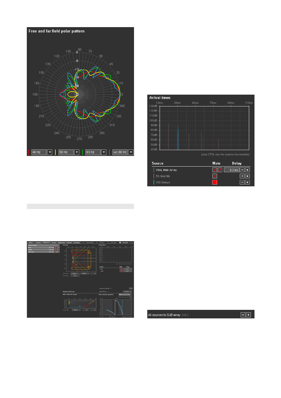
Polar diagram
Use the Alignment page to calculate the correct time
alignment between the SUB array and a selectable flown
array with the help of a phase matching procedure (refer to
section 10.11.1 Time alignment of SUB arrays on page
39).
10.11 Alignment page
For a complex system consisting of multiple sources it is
essential to time align the different parts in a useful way.
ArrayCalc provides a dedicated 'Alignment' page to help
you find a useful alignment strategy and finally deduce
starting values.
Alignment
The left side of the page contains a fully operable copy of
the project, room and source settings of the project.
Selecting the test point for array alignment
Within a copy of the Top view diagram, you can place a
test point, either by clicking in the diagram and/or by
moving the test point around using the arrow buttons next to
its x/y coordinates or by directly entering numerical values.
The z-coordinate is calculated based on the x/y position
and on the presence of a listening plane at this position.
When you move the point, the algorithm keeps it on the
same plane as long as possible. If the end of a plane is
reached, it jumps onto the next plane in the direction of
moving. The Current plane field shows the name of the
plane on which the test point is currently located.
Arrival times diagram
Arrival times diagram including point sources
The arrival times diagram shows the first arrival of acoustic
energy reaching the test point in milliseconds for all arrays
or individual sources in the project provided they are
unmuted. Underneath the diagram you can define mute
and delay settings for each array. In case of an array, both
functions are operable copies of the same functions in the
array settings dialog of each array.
The Delay settings can be defined by entering data directly
into the relevant field of each array or using the +/--
buttons. Holding down the CTRL key (Apple key for
Macintosh) while clicking the +/-- buttons switches from fine
to coarse increments.
In case of a point source group, the Mute switch here mutes
or unmutes the entire group. If you want to mute/unmute
the individual sources of the group, you have to go to the
appropriate point source settings dialog. The delay buttons
for a point source group increment/decrement the delay
values for all sources of the group while keeping their
settings relative to each other. As a result, a numeric data
input field is not available here.
In the above example, the test point is located at a position
to align the "Outfill" array to the "Main Array" array. The
first arrival time from the left side of the paired "Outfill"
array is around 110 ms, while the arrival time of the left
side of the paired "Main L/R" array is around 114 ms. That
means, approximately 4 ms of delay have to be added to
the "Outfill" array to set a correct time arrival for this test
point position.
TI 385 (6.0 EN) d&b Line array design, ArrayCalc V8.x
Page 38 of 54