5 array view and load distribution, 6 top view diagram for arrays, 7 profile at array aiming – d&b TI 385 d&b Line array design User Manual
Page 25
V, Y and Q Flying adapter
If a small V, Y or Q-Series array allows the optional use of
the Z5385 V Flying adapter/Z5394 Y Flying adapter/
Z5156 Q Flying adapter, the pickpoint information is
displayed on the Rigging plot page provided the
corresponding array is selected on this page. Refer to
section 10.15 Rigging plot page on page 44.
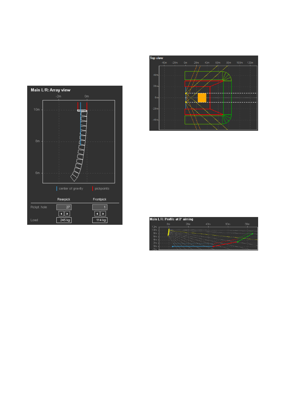
10.7.5 Array view and load distribution
Array side view with load parameters and pick point
settings
The array side view shows the mechanical setup of the
cabinets including the center of gravity of the whole array
(blue). A cabinet being edited in the array section is
highlighted in yellow.
Rearpick / Frontpick
The pick points for dual hoist support can be set to optimize
load distribution. Depending on the exact hole position of
the Load adapters on the Flying frame, the loads for each
hoist are calculated. The load distribution can be modified
by moving the pick points.
xA-Series arrays
The orientation of the Z5415 Flying bar adapter xA
changes according to the center of gravity of the array.
If both orientations are possible, the rearward orientation is
chosen.
10.7.6 Top view diagram for arrays
Top view of listening planes and arrays
The top view shows the active listening planes, the position
of the arrays and their horizontal coverage area (nominal –
6 dB isobars).
All arrays of a project are shown, the currently selected one
is colored, all others are shown in gray. The dashed beams
indicate the main axis of each array, the yellow (gray)
dotted lines the coverage area of the uppermost cabinet
and the orange (gray) dotted lines the lowest cabinet, in
this case a J12. The coverage lines end when they hit a
listening plane that is set to absorbent. (See section
Listening plane properties on page 18).
10.7.7 Profile at array aiming
Profile view at horizontal aiming of selected array
The profile view shows a cross section through the active
listening planes in the direction of the selected array's main
axis with the listener ear height indicated. The x scaling is
always relative to the array's position and therefore does
not necessarily correspond to the absolute scaling of the
top view diagram. Each dashed beam marks the main axis
of one cabinet. The beam of a cabinet being edited in the
array section is highlighted in yellow.
TI 385 (6.0 EN) d&b Line array design, ArrayCalc V8.x
Page 25 of 54