11 array eq / cpl, 12 level adjustment (lev/db) – d&b TI 385 d&b Line array design User Manual
Page 28
At lower humidity values absorption by air increases
therefore the distances at which the respective HFC settings
provide a correct equalization will be shorter.
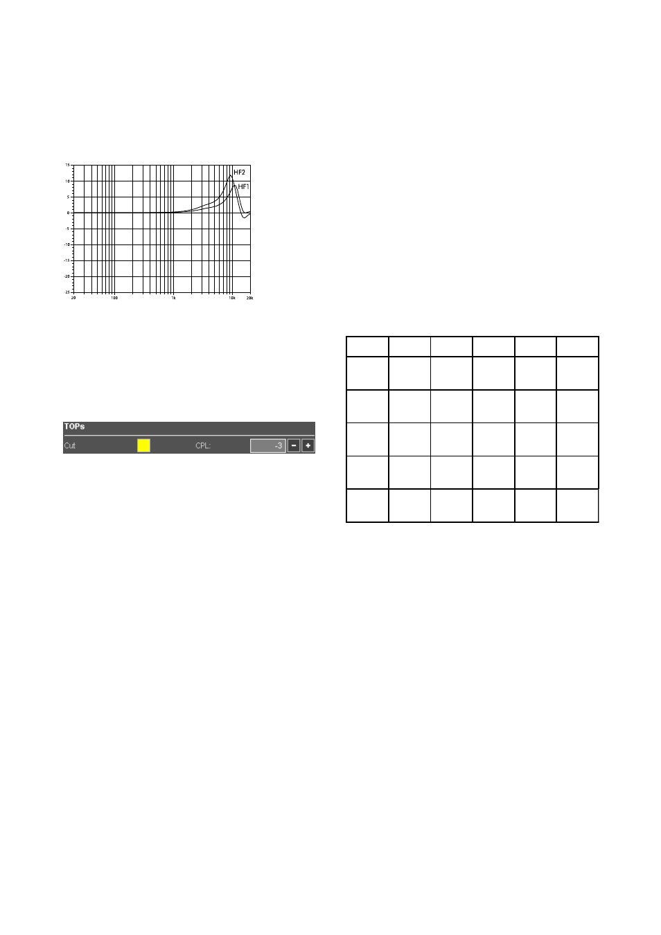
The HFC2 compensation in the J8/J12, V8/V12, Y8/Y12
T10 and 10AL(-D) Line setups include a bandwidth
limitation to approx. 10 kHz to keep the necessary boost
within meaningful limits not wasting the system's headroom.
Example of frequency response correction
of the HFC circuits
Note: When ArrayProcessing is enabled, the HFC
function is not available. Air absorption effects and
their
compensation
are
included
in
the
ArrayProcessing algorithm.
10.7.11 Array EQ / CPL
Six J8/J12 cabinets arrayed vertically with up to 12° total
splay angle produce a flat frequency response. Longer
columns with more total splay will boost low and low/mid
frequencies. The adjustable CPL function in the amplifier
compensates for these effects. While setting the splay
angles the Array EQ "Coupling" parameter (CPL, 0...–9 dB)
can be set to a useful attenuation of lower frequencies to
achieve a balanced sound. The setting of the CPL
parameter affects the frequency response of the array, the
curves of the SPL plot shifting accordingly.
The same principle applies to Q and T arrays. CPL should
be used with arrays of four or more cabinets and a total
splay of more than 15°.
Matching the 500 Hz curve (selectable for the low/mid
curve) with the 1000 Hz curve (high/mid) usually provides
a good start value for the CPL setting. The CPL parameter is
available in the d&b amplifier configurations for J-, Q- and
T-Series and should be set there correspondingly. All
amplifier channels powering one array must be set to the
same CPL value.
10.7.12 Level adjustment (Lev/dB)
After having set the splay angles, you may still find a
significant increase in level very close to the array. It can be
adjusted by decreasing the level of the lower cabinets of
the array. When applying this to ArrayCalc, consider that
usually several cabinets are linked to the same amplifier
channel, so set the levels equally for all cabinets which will
be connected in parallel.
If you want to change the level of the whole array to modify
the coverage between different arrays of the setup, you can
use the relative Level group control. Don´t forget the level
of the SUBs if there are any in the array.
Note: Keep in mind that for a lot of applications a
certain increase in level towards the front is expected or
even required, in particular with ground stacked
subwoofers and high stage levels.
Please note that the effect of the level adjustment on the
SPL distribution may decrease when the system is driven
to its limits.
Setting the SPL distribution purely by splay angles
provides a more consistent dynamic behavior.
10.7.13 Horizontal arrays of J8, V8, Y8, Q1 and
T10 columns
The recommended horizontal angles between adjacent
arrays are listed in the following table matrix:
Series J
V
Y
Q
T
J
50°-
70°
50°-
70°
50°-
70°
45°-
65°
50°-
75°
V
50°-
70°
50°-
70°
45°-
65°
50°-
75°
Y
50°-
70°
45°-
65°
50°-
75°
Q
40°-
60°
50°-
70°
T
60°-
80°
Smaller horizontal angles between the columns will give a
smaller horizontal coverage area, but will produce higher
sound pressure on the center axis and increased comb filter
effects between the arrays. Larger horizontal angles with
careful level tuning can help to seamlessly align outfill
arrays while at the same time compensating for the reduced
distances these arrays have to cover.
The array configurations should be thoroughly adapted to
the actual room acoustics and requirements. In order to
keep diffuse sound low, the total coverage angle should
only be as wide as necessary to cover the audience area.
The smoothest coverage will be achieved if both columns of
a horizontal array have identical vertical setups. Of course
this is often not realistic. If the columns are considerably
different in length or vertical aiming a distance of at least
3 m (10 ft) between their lifting points will reduce audible
interference effects.
In general, an equal height of the bottom boxes of two
adjacent columns gives the smoothest transition for close
audience areas where interference effects are most audible.
TI 385 (6.0 EN) d&b Line array design, ArrayCalc V8.x
Page 28 of 54