d&b TI 385 d&b Line array design User Manual
Page 36
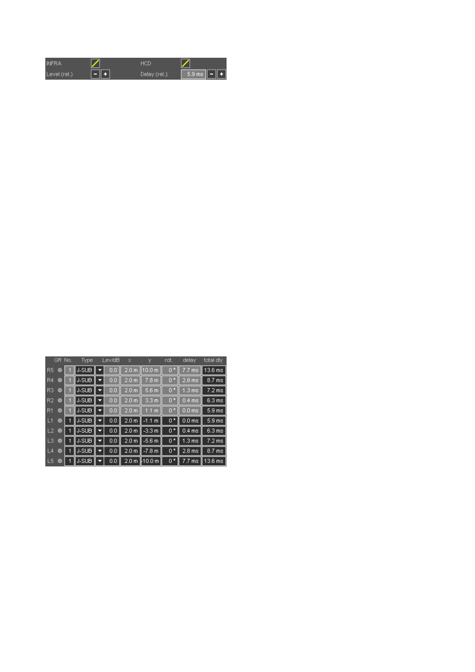
SUB array group controls
Depending on the type of subwoofers selected, group
controls are available which define the main amplifier
settings for the array. The simulation result changes in
accordance with the settings. Note that the level mapping
diagram which is displayed when you select the SUB array
option on the Arrays tab shows a relative level distribution
only.
As a result, it does not change if, for example, the overall
input signal level is altered.
Group controls are
Mute: Located in the headline in order to be available
even if the array is not opened for editing.
Relative delay value for the array: The value is
relative in order to align the SUB array to a selected array
while keeping the arc-delays.
Relative levels: Increments/decrements the levels of all
sources by 0.5 dB.
Loudspeaker specific amplifier controls such as:
Switch 1: Defines the upper frequency extension of the
selected system, i.e. "INFRA", "70 Hz" or "100 Hz" modes.
Switch 2: When available, defines the dispersion
characteristics of the selected subwoofer system, i.e. HCD
(hypercardioid) mode.
Cabinet setup
Cabinet setup matrix
GR indicators
Each source position has a yellow GR LED which indicates
when a particular amplifier channel has reached its limit for
the given signal level with one of the simulated input signals
selected for the 2D and 3D SPL plots.
A possible Gain Reduction is not considered in the SPL
calculations, i.e. will not limit a cabinet´s calculated output
and will therefore not modify the SPL distribution.
Consequently, with (too) many GR LEDs on, the calculated
and displayed level distribution might actually not be
attainable.
Whenever a GR LED lights up for a cabinet within an array,
the GR LED in the headline is activated even if the array is
not opened for editing.
No. of cabinets
Defines the number of cabinets for the respective source
position. For CSA arrangements consisting of Q-SUB or
B2-SUB subwoofers this number is set to 3 and locked.
Cabinet type
Shows the type of the selected subwoofer system. In case of
a mixed J-SUB / V-SUB / J-INFRA array you can select the
specific cabinet type for each individual position.
Level/dB
The gain to be set on the respective amplifiers / amplifier
channels.
Note: Do not try to achieve the desired dispersion by
using individual cabinet level settings. Use identical
levels for all amplifiers, otherwise the array dispersion
will change when the system is driven to its limits.
x/y columns - manual positioning
Subwoofer x/y positions can also be defined manually. This
may be necessary if SUB arrays have to be fitted into
existing stage sets, or if single obstacles have to be taken
into account.
After placement is modified manually, the displayed source
spacing and the frequency limit for pattern control are not
necessarily valid any more.
The mapping and the polar plots should be checked for
increased lobing at the upper end of the frequency range.
Rotation - rotation angle
Take advantage of directional subwoofers: For very wide
dispersions, additional rotation of subwoofers can help to
keep the energy distribution smooth and even. Progressive
rotation towards the outermost subwoofers should then be
applied. In many applications a rotation by 60° for the
outermost SUBs and 30° for the ones next to them makes a
great difference. Observe the mapping and polar plots
while working on this. Avoid rotations by more than 90°.
When setting up the subwoofers physically, make sure you
rotate them about their center axes. Do not move the center.
Total delay
This column indicates the actual values to be set at the
respective amplifier channels. It is the sum of all the
individual delay values within the array plus the overall time
alignment to the main system. Refer to section 10.11.1 Time
alignment of SUB arrays on page 39.
TI 385 (6.0 EN) d&b Line array design, ArrayCalc V8.x
Page 36 of 54