The v-series line array, 1 number of cabinets required, 2 v-sub subwoofer setup – d&b TI 385 d&b Line array design User Manual
Page 6
3. The V-Series line array
The V-Series consists of three different loudspeakers: the V8
and V12 loudspeakers and the V-SUB subwoofer. The V8
and V12 are mechanically and acoustically compatible
loudspeakers providing two different horizontal coverage
angles of 80° and 120°. The dispersion of both systems is
symmetrical and well controlled to frequencies down to
250 Hz, their bandwidth reaching from 65 Hz to 18 kHz.
V-Series loudspeakers can be operated with d&b D12,
D20 or D80 amplifiers. With D20 and D80 amplifiers d&b
ArrayProcessing is available.
In the vertical plane the V8 and V12 loudspeakers produce
a wavefront that allows splay angle settings ranging from
0° to 14° (1° increments). An array should consist of a
minimum of four cabinets - either V8, V12 or a combination
of both.
The V8 with its 80° horizontal dispersion and high output
capability can cover any distance range up to 100 m
(330 ft) depending on the vertical configuration of the
array and the climatic conditions.
The V12 offers a wider horizontal coverage which is
particularly useful for short and medium throw applications.
Using a combination of V8 and V12 cabinets enables the
user to create a venue specific dispersion and energy
pattern.
The V-SUB cardioid subwoofer extends the system
bandwidth down to 37 Hz while providing exceptional
dispersion control either flown or ground stacked in arrays
or set up individually.
The J-INFRA cardioid subwoofer is an optional extension to
a V8/V12/V-SUB system. It is used in ground stacked
configurations and extends the system bandwidth down to
27 Hz while adding impressive low frequency headroom.
3.1 Number of cabinets required
The number of V-Series loudspeakers to be used in an
application depends on the desired level, the distances and
the directivity requirements in the particular venue. Using the
d&b ArrayCalc calculator will define whether the system is
able to fulfill the requirements.
Depending on the program material and the desired level,
additional V-SUBs will be necessary to extend the system
bandwidth and headroom. In most applications a V-SUB to
V8/V12 ratio of 1:2 is sufficient. Distributed SUB arrays
may require a higher number of subwoofers, such as a
V-SUB to V8/V12 ratio of 2:3.
When additional J-INFRA systems are used, one cabinet
provides the very low frequency extension for two V-SUB
subwoofers, thus generally reducing the total number of
V-SUBs required.
3.2 V-SUB subwoofer setup
V-SUB cabinets can be used ground stacked, as a
horizontal SUB array or integrated into the flown array,
either on top of a V8/V12 array or flown as a separate
column.
The V-SUB cabinet offers a cardioid dispersion pattern
throughout its entire operating bandwidth.
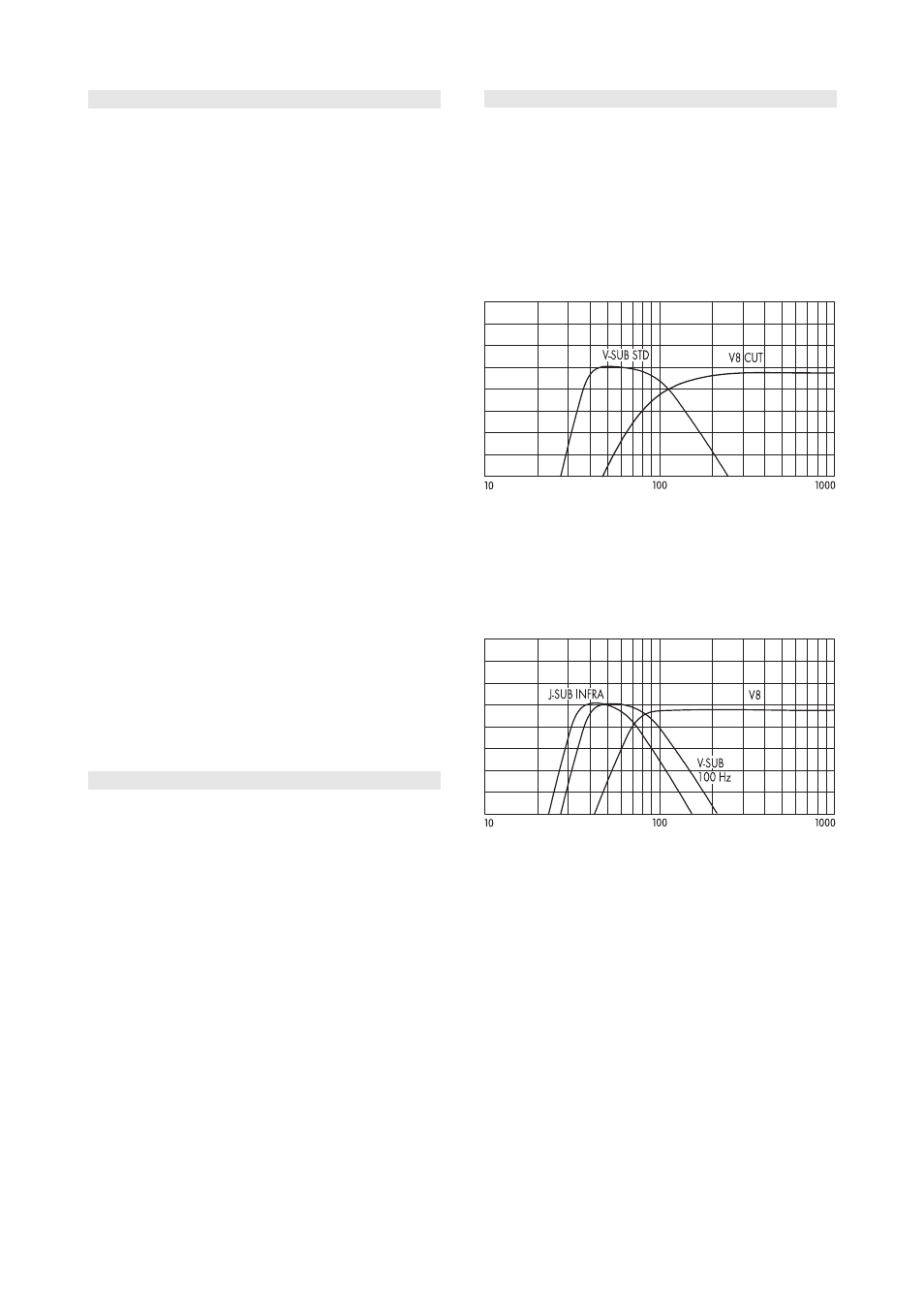
When used with additional subwoofers, the V8/V12 system
should be operated in CUT mode to gain maximum
headroom at low frequencies.
V8 / V-SUB crossover setup
When maximum low end headroom is not an issue, the V8/
V12 system can also be operated in standard mode (full
range, i.e. CUT not selected) and additional V-SUB cabinets
in 100 Hz mode or J-SUB cabinets in INFRA mode can be
used to extend the system bandwidth down to
38 Hz/32 Hz.
V8 / V-SUB / J-SUB crossover setup, full range
TI 385 (6.0 EN) d&b Line array design, ArrayCalc V8.x
Page 6 of 54