d&b TI 385 d&b Line array design User Manual
Page 21
Headline
In each headline of the array settings dialogs, the name of
the respective array can be edited directly by clicking on
the text on the left.
The headline also contains an ArrayProcessing LED (AP
LED) which indicates whether ArrayProcessing is enabled
for this particular array, a Gain Reduction LED (GR LED)
and individual Mute switches for the entire array(s). Their
functions are described in detail in sections 10.7.3 Gain
Reduction indicator GR on page 27 and section 10.7.9
Maximum SPL and headroom on page 27.
ArrayCalc supports different array setups including flown
subwoofers or ground stacked configurations. The type of
system and its mounting can be selected independently for
each array / pair of arrays.
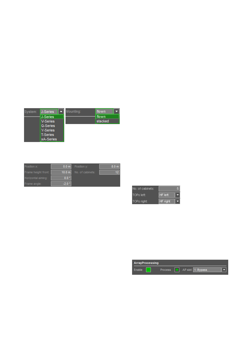
Selection of system and mounting
Array positions, aiming and No. of cabinets
Position x / Position y
Defines the coordinates of the top front of the array. When
the Pair option is enabled, the y coordinate is always set to
a positive value and the second array will be located at the
negative y value.
Frame height front
Height above ground of the top front edge of the Flying
frame (trim height).
Horizontal aiming
Horizontal aiming of the array. Positive angle: aimed
towards positive y values. (For pairs of arrays it refers to the
house left array, i.e. positive value: rotated inwards,
negative value: outwards). To calculate SPL over distance,
ArrayCalc uses the projection of the listening planes in the
direction of each array´s horizontal aiming.
Frame angle
Sets the vertical aiming of the entire array. The vertical
orientation of the uppermost cabinet is identical to the frame
angle.
A line array produces a precisely shaped wavefront
following the mechanical arrangement of the cabinets. The
cut off at the upper and lower limits of the vertical
dispersion of a column is very sharp, and therefore accurate
aiming is absolutely essential to address the desired
audience area.
The first parameter to set is the flying frame angle and
height. For best results the top cabinet of the column should
aim at the farthest point in the audience area. Aiming the
Flying frame up to 2° above this point sometimes gives a
smoother coverage and can help to stabilize the level
distribution under changing climatic conditions outdoors.
Check the SPL plot for the effect but at the same time
consider a possible increase of reflections from the rear
walls.
No. of cabinets
Total number of SUB and TOP cabinets used in the array.
The final selection of the cabinet type for each individual
position is made in the cabinets section.
With Q1 arrays a Q7 loudspeaker can be inserted at the
very bottom of the column (horizontally mounted with
rotated horn). The maximum splay of 14° is used here.
Compared to a Q1 used in the same position this setup
gains about 10° more coverage to the front for high
frequencies. The Q7 has to be driven by a separate
amplifier channel in Q7 configuration.
xA-Series: No. of cabinets / TOP cabinet
orientation
In an xA-Series array, SUBs
and TOPs may be arranged
in any order within the
array.
The TOPs of the xA-Series have a biaxial design. Although
they do not provide mechanical symmetry, their dispersion
design is highly symmetrical within the nominal dispersion
area, the level roll-off beyond that area is inevitably not
perfectly symmetrical. To enable a symmetrical setup for
stereo systems, the cabinet orientation may be reversed. In
the default orientation, the HF waveguide is located to the
left, viewed from the audience side.
ArrayProcessing
Enable:
Enables the ArrayProcessing option for this particular array
or pair of arrays.
Note: ArrayProcessing is available for the J, V and Y-
Series and can be enabled for flown arrays consisting
of a minimum of 4 cabinets.
TI 385 (6.0 EN) d&b Line array design, ArrayCalc V8.x
Page 21 of 54