18 low frequency timer 1 and 2, Table 5-19, Low frequency timer settings – Artesyn ATCA-9305 User's Manual (May 2014) User Manual
Page 118: Management processor cpld
Management Processor CPLD
ATCA-9305 User’s Manual (10009109-07)
118
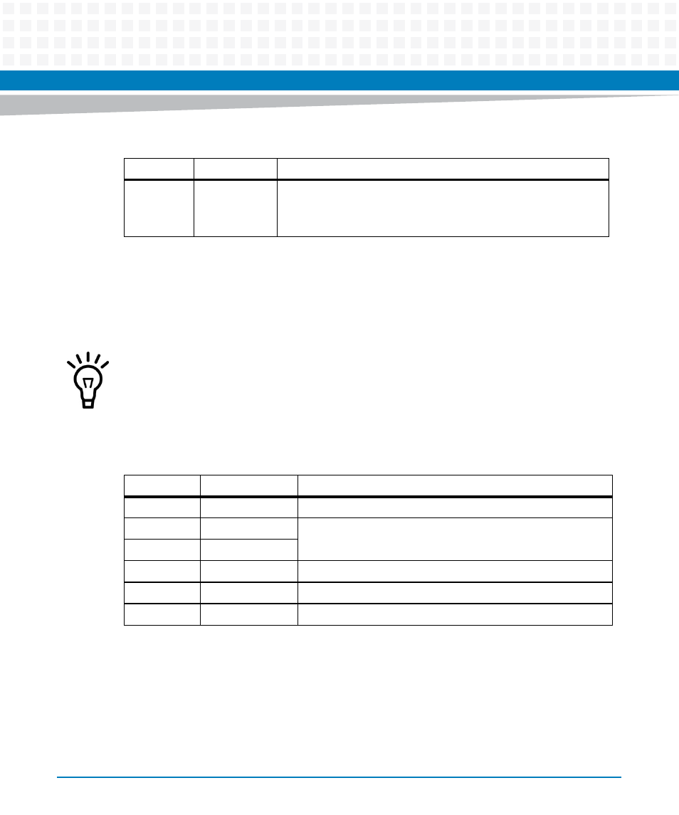
5.1.18 Low Frequency Timer 1 and 2
Registers LFTR1 (0x58) and LFTR2 (0x5C) are timers. They determine how many 50 μs intervals
you want before the next interrupt on Cavium GPIO5.
0
I2CSCL
I
2
C Clock line
0 Drive a 0 onto the I2C SCL line
1 Drive a 1 onto the I2C SCL line
Table 5-18 Miscellaneous Control (0x54) (continued)
Bits
Function
Description
Unless the frequency is set to 0, there is always one 50 μs interval. This is the reason for the
register setting being 1 less than an even hundred, for example 199 rather than 200.
Table 5-19 Low Frequency Timer Settings
Frequency
Set Register
Comments
0
Off
Never interrupts
1 Hz
19999 (0x4E1F)
These frequencies require the use of both registers
10 Hz
1999 (0x7CF)
100 Hz
199 (0xC7)
1 KHz
19 (0x13)
10 KHz
1
This equals two 50 ìs time units (default)