Back panel connectors, 1 overview, 2 zone 1 – Artesyn ATCA-9305 User's Manual (May 2014) User Manual
Page 213: 1 overview 8.2 zone 1, Table 8-1, Zone 1 connector, p10 pin assignments, Figure 8-1, Zone 1 connector, p10, Chapter 8
Chapter 8
ATCA-9305 User’s Manual (10009109-07)
213
Back Panel Connectors
8.1
Overview
There are multiple connectors on the ATCA-9305, reference
for their location. The
back panel connectors, Zones 1 through 3, are described in this chapter. Whether individual
back panel connectors are populated on the ATCA-9305 depends on the specific product
configuration.
8.2
ZONE 1
Connector P10 provides the AdvancedTCA Zone 1 power (dual redundant -48 VDC) and
system management connections. Four levels of sequential mating provide proper
functionality during live insertion or extraction, see
.
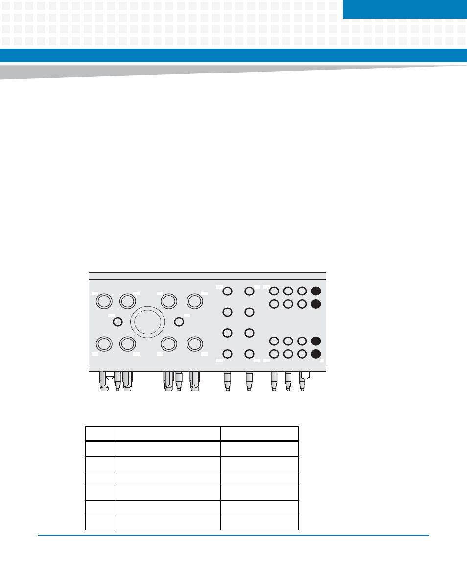
Figure 8-1
Zone 1 Connector, P10
Table 8-1 Zone 1 Connector, P10 Pin Assignments
Pin
Signal
Insertion Sequence
1
reserved
NA
2
reserved
NA
3
reserved
NA
4
reserved
NA
5
HA0
third
6
HA1
third
1
13
17
21
25
28
30
27
33
32
34
31
29
26
24
20 16
4