28 ipmp/ipmc gpio control, 29 lpc bus control, 28 ipmp/ipmc gpio control 5.1.29 lpc bus control – Artesyn ATCA-9305 User's Manual (May 2014) User Manual
Page 125: Table 5-29, Ipmp/ipmc gpio control (0x8c), Table 5-30, Lpc bus (0xd0), Management processor cpld
Management Processor CPLD
ATCA-9305 User’s Manual (10009109-07)
125
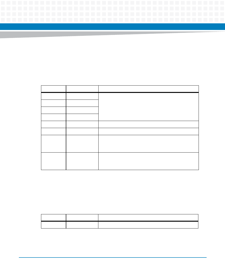
5.1.28 IPMP/IPMC GPIO Control
This register provides access (if required) to signals between the KSL CPLD and the IPMP, as well
as to signals between the KSL CPLD and the IPMC. The lower two bits can request request the
power down of a Cavium core from the sticky reset register.
5.1.29 LPC Bus Control
This is the control register for the 4-bit LPC bus. It allows for communication with the IPMC
controller from the management CPU.
Table 5-29 IPMP/IPMC GPIO Control (0x8C)
Bits
Function
Description
7
IPMC2KSL4
Input only
6
IPMC2KSL3
5
IPMC2KSL2
4
IPMC2KSL1
3
IPMP2KSL4
Output only
2
IPMP2KSL3
Output only
1
IPMP2KSL2
Power-down signal for Cavium 2 (output)
Assert high to shut down the core. The sticky Cavium reset
also causes this to be asserted.
0
IPMP2KSL1
Power-down signal for Cavium 1 (output)
Assert high to shut down the core. The sticky Cavium reset
also causes this to be asserted.
Table 5-30 LPC Bus (0xD0)
Bits
Function
Description
7
LPCIE
LPC Interrupt Enable