Maintenance – Beisler 1360-4 User Manual
Page 59
C-19
Service Instructions Automatic Multi-Head Serging Machine1365-4
Beisler GmbH
C.5
Maintenance
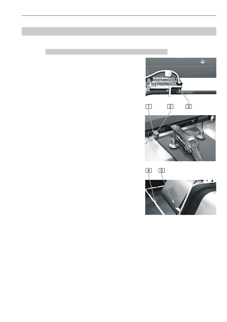
C.5.13Adjusting the cross transport photocells
Fig. 12: The movement of the cross transport is control-
led by two photocells and an initiator:
Initiator for the basic position 3
Photocell for the wait position 2 in front of the B
machine
Photocell for the transfer position 4 at the B machi-
ne for transferring the sewing piece to the swing arm
Initiator for basic position 3:
The position of the initiator that determines the cross
transport basic position cannot be changed. Two
screws secure the initiator in an opening of the backet.
Photocell for wait position 2:
The position of the photocell for the wait position can be
changed. The light beam of the photocell should always
be positioned to the center of the film disk 1.
To position the photocell:
1. Loosen the locating screw of the photocell clamp
block.
2. Position the photocell.
3. Tighten the locating screw of the photocell clamp
block.
Photocell for transfer position 4:
The photocell that determines the transfer position at
the B machine and therefore the start of the swing arm
movement is attached to the protective strap of the sli-
ding panel. The sensor area lies within the rectangular
reflective film surface 5 at the sliding panel.
1. Loosen the retaining screw of the photocell moun-
ting bracket.
2. Position the photocell.
3. Tighten the retaining screw of the photocell moun-
ting bracket.
Fig. 12