Maintenance – Beisler 1360-4 User Manual
Page 61
C-21
Service Instructions Automatic Multi-Head Serging Machine1365-4
Beisler GmbH
C.5
Maintenance
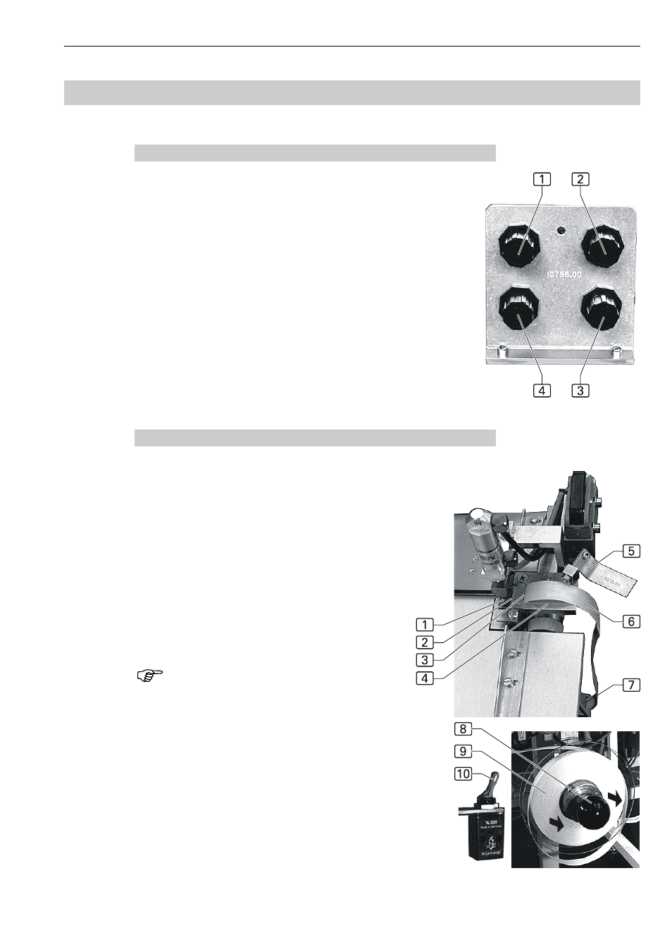
C.5.15 Setting the pressures
Fig. 14: To improve the gliding characteristics of the sewing pie-
ces, the working plate has six compressed-air nozzles near the A
and B machines. The air blows from below against the sewing
pieces; the resulting air cushion reduces friction during transport.
The pressure depends on the weight of the material used.
The pressure that the rollers of the two transport units apply to
the working plate can be matched to fit the thickness of the mate-
rial used.
The required air pressure that can be set with separate valves
must be determined by trial and error. To change the pressure:
1. Pull the valve knob out to unlock the valve, then set the pres-
sure by rotating the valve.
2. To lock the valve, push the valve knob in.
1 Transport unit, A machine
2 Transport unit, B machine
3 Nozzles in B machine working plate
4 Nozzles in A machine working plate
C.5.16 Inserting the bonding strip at the bonding station
Fig. 15: The bonding strip rolls off a drum. The sepa-
rator removes the strip from the backing tape and pu-
shes it over the lower stamp 1 of the heating modu-
le. To insert the bonding strip:
1. Remove the disk 8 from the drum; the disk is
merely pushed on.
2. Attach the bonding strip roll 9 to the drum and
push the disk back onto the drum.
3. Rotate the pressure pad 5 of the guide 4 side-
ways.
4. Separate the bonding strip from the backing tape
6 and route the strip through the slot 3.
5. Rotate the pressure pad back onto the guide and
cut the bonding strip at the edge 2 of the guide.
NOTE - Position of the lower stamp!
The proper function of the bonding unit
is only ensured if the lower stamp is in
the lowered position. By actuating the
switch 5, the lower stamp can be mo-
ved to the upper or lower position.
For cleaning, the lower stamp is moved
to the upper position, and the bonding
station heating module is switched off.
Fig. 14
Fig. 15