Fronius IG 300 User Manual
Page 61
53
Example
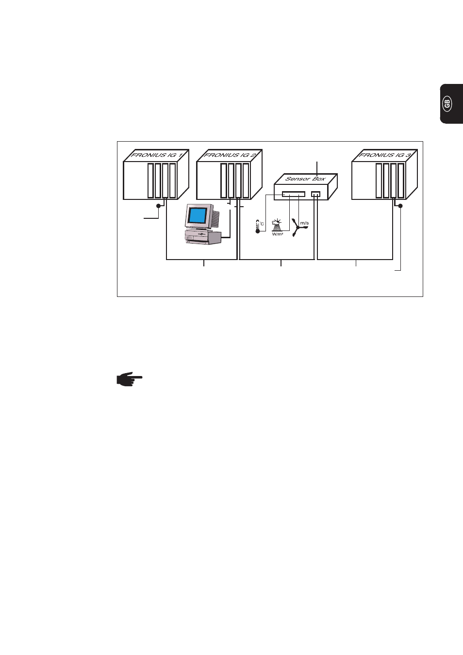
Example: Logging and archiving data from the inverter and sensor using a datalogger
card and sensor box.
Within the FRONIUS IG, the plug-in cards communicate via its internal network. External
communication (LocalNet) is implemented using the COM cards. Each COM card has
two RS-485 interfaces as its input and output. RJ45 plug connectors are used to connect
to these cards.
The first FRONIUS IG with COM card can be up to 1,000 m away from the last FRONI-
US IG with COM card.
Datalogger
COM card
PC
(5)
(5)
(6)
(6)
(6)
COM card
COM card
(5) Terminal plug
(6) Data cable
Sensor box in
external housing
IN
OUT
OUT
IN
OUT
IN
PC IN OUT
RS-232
-
Configuration of a FRONIUS IG with datalogger card
(Figure: FRONIUS IG 2)
-
Configuration of all FRONIUS IGs, each with a COM card
The datalogger has two RS-232 interfaces for connecting to a PC and a modem.
NOTE! It makes no difference which card is installed in which slot
However, the following point should be borne in mind:
-
The FRONIUS IG may contain only one COM card
-
A network may contain only one datalogger
More detailed information on the individual add-on system components can be found in
the relevant operating instructions or on the internet at www.fronius.com.
Fig.6
Example of data communication via the LocalNet