Model 9850kxtw1 shear valve configuration, Model 9850kxtw1 shear valve configuration -10, Model 9850kxtw1, refer to – Gasboy Atlas Fuel Systems Installation Manual User Manual
Page 40: Model 9850kxtw1 shear, Valve configuration, Figure 6-1
Installation
Model 9850KXTW1 Shear Valve Configuration
Page 6-10 MDE-4331M Atlas® Fuel Systems Installation Manual · September 2014
4
Double-check the alignment of pipes, conduit, and frame (see
Note: Misaligned piping can result in a leak.
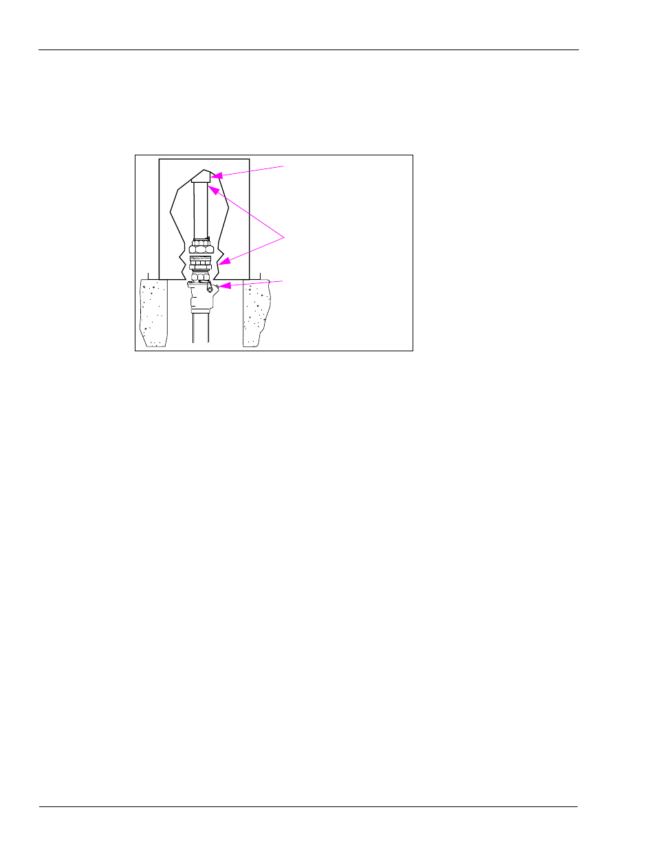
Figure 6-1: Shear Valve at Grade
1-1/2-inch NPT Coupling on unit
Installing contractor-supplied
black iron piping to coupling,
including union
Shear Valve with shear
point installed flush with
grade ±3/4-inch
2-inch NPT Coupling on Ultra-Hi
Gallonage unit
Note: It is a mandatory code requirement that the shear section of the shear valve be within
+/- 3/4-inch (or to the shear valve manufacturer’s requirement, whichever is tighter)
from the plane of the bottom of the base of a dispenser.
5
Connect and tighten the union halves (see
6
Tighten the anchor bolts. Ensure that the shear valves are properly tightened to the pit box or
the shear valve anchor bracket.
Model 9850KXTW1 Shear Valve Configuration
The Atlas Ultra-Hi with twin inlet manifold requires a special inlet configuration because of
the limited base to manifold distance. Gasboy recommends the Marrison Bros. 2-inch 636F
shear valve with a union attached at the bottom of the valve, to connect to the service system
piping.
Note: This configuration is for the Atlas Model 9850KXTW1 only. All other Atlas models must
use a standard inlet configuration.