Gasboy Atlas Fuel Systems Installation Manual User Manual
Page 56
Installation
Calibration
Page 6-26 MDE-4331M Atlas® Fuel Systems Installation Manual · September 2014
Adjusting Calibration for Standard, Hi-Flow, and Super-Hi Models
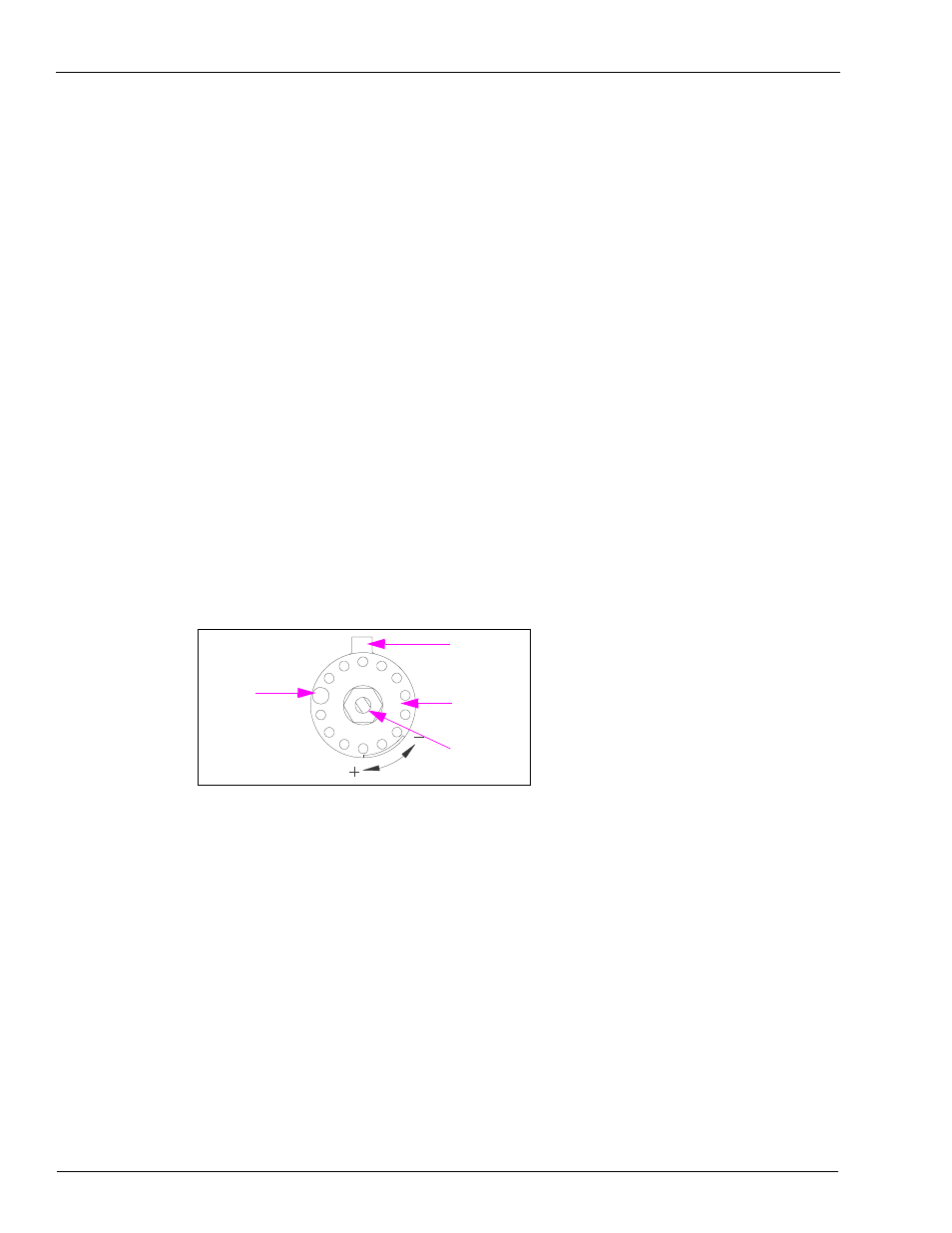
If calibration is required, remove the restraint (seal-wire from locking pin) on the calibration
wheel located on each meter. Each pin hole represents one cubic inch of fluid. Moving the
calibration wheel counter-clockwise, one pin hole creates a negative of one cubic inch of fuel;
when turning the calibration wheel clockwise, one pin hole adds one cubic inch of fuel to the
total flow. To calibrate the meter, the pin must first be removed and the wheel turned in the
required direction to retard or add to the rate of product flow. Reinsert the pin into the hole in
the wheel and test the new setting. After the correct flow of the product has been established,
the pin and wheel must be wired and a seal put in place (if required, it is the owner’s
responsibility to report this device to the local W&M officials for their inspection before the
unit is put into service).
Atlas (Gallon Unit of Measure)
For electronic retail
units, temporary pricing must have already been entered into the unit to
allow dispensing and calibration. Refer to
“Calibration Adjustment for Ultra-Hi Models”
on
Currently produced Atlas pumps/dispensers are precalibrated to US gallons (calibration
verification is still required) and programmed to default programming values. They may be
operated and purged in normal mode after entering the prices. When the unit is in gallon mode,
purging can be done for units eventually to be converted to metric mode.
Figure 6-9: Calibration Wheel
Index Plate
Index Disc
Do not apply
wrench for
calibration.
Seal Pin