Gasboy TopKAT Fuel Management System Installation User Manual
Page 69
Advertising
MDE-4319E TopKAT™ Fuel Management System Installation Manual · August 2008
Page 63
Wiring Diagrams
Mechanical Interface Option
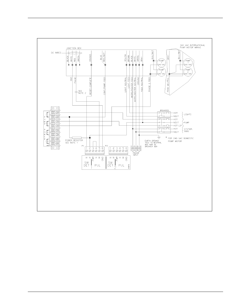
Figure 7-18: Wiring Diagram: 9853HC, 9840 Pumps
Diagrams shown are for Q Model pumps. If your pump is an A model, DC Junction box will be separate.
Notes:
1. The power resistor assembly is 8.2 kilo-ohm, 10 W (part number C05818) for 115/230 VAC domestic units and 30 kilo-ohm,
10 W (part number C06683) for 230 VAC International units.
2. Before applying power, the TopKAT Pump Control PCB jumpers must be set for electronic pulser as shown in
. Failure to properly set the jumpers will damage the TopKAT.
3. The wire colors may vary. Refer to current pump wiring diagrams.
Advertising
This manual is related to the following products: