Caution – Gasboy TopKAT Fuel Management System Installation User Manual
Page 94
Mechanical PCU Option
Pump Control I/O PCB
Page 88
MDE-4319E TopKAT™ Fuel Management System Installation Manual · August 2008
4
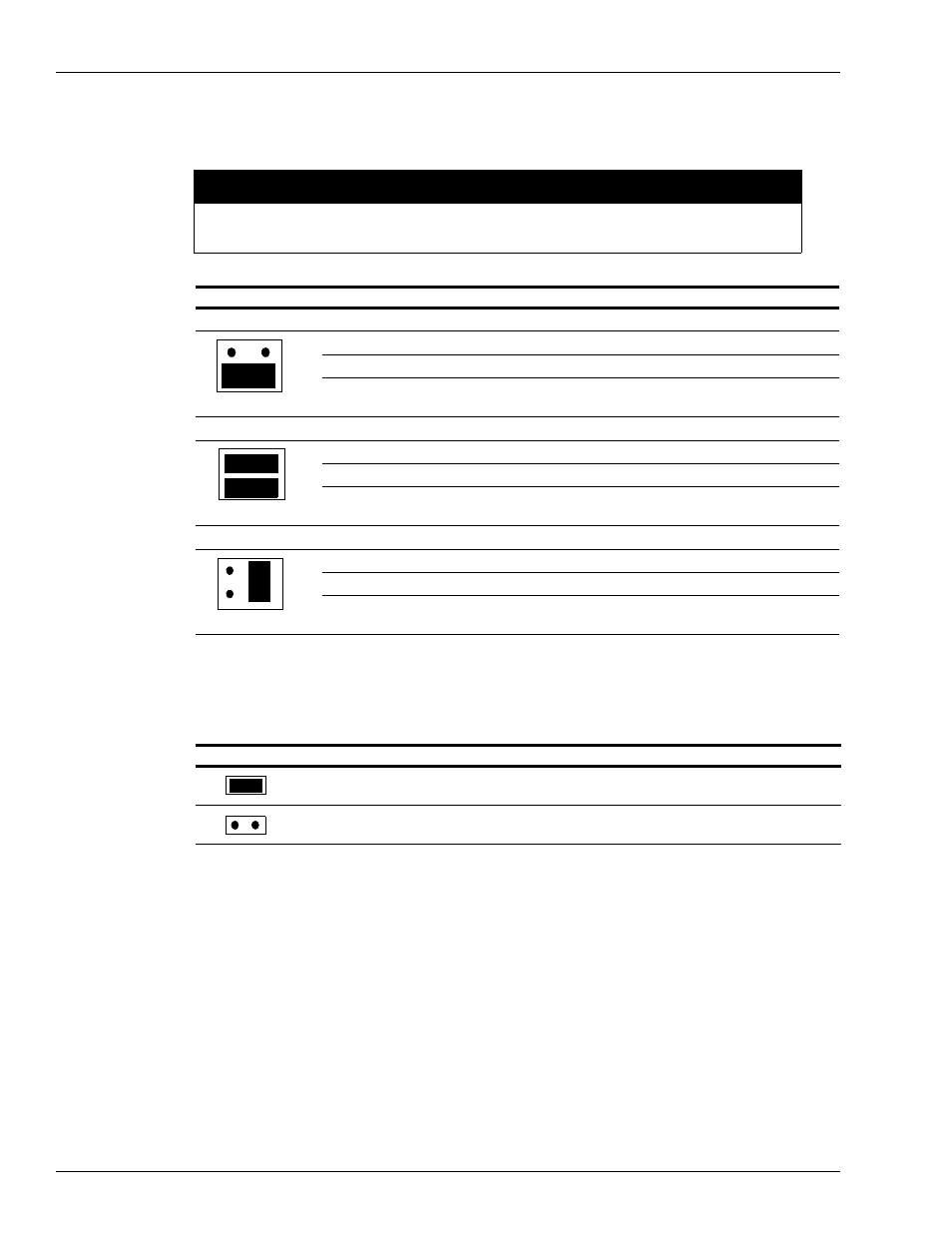
Pulse Connection: Verify if the K1 through K4 jumpers (pulse type jumpers) match the Type
pulser being used for each pump position. Use the following table to determine your settings.
K1 to K4 jumpers must be set in the configurations shown below before turning on power to the
PCU or damage to the system components may occur.
CAUTION
Jumper
Pin
Function
Voltage
VR Reed Switch Pulser, 1871 Series
P
Pulser signal input (sink)
12 VDC square wave signal when pulsing
+
No connection
G
DC ground for pulser
DC ground
VR Electronic Pulser, 7671 Series
P
Pulser signal input (sink)
12 VDC square wave signal when pulsing
+
+12 VDC supply voltage for pulser
+12 VDC
G
DC ground for pulser
DC ground
VR Totalizer Pulser, 7874 Series
P
Pulser signal input (sink)
Square wave signal when pulsing
+
Voltage for opto-isolator from pulser
Voltage level of pulser
G
DC ground for pulser
DC ground
5
Debounce Configuration: Verify if the K5 jumper (debounce) is set properly as per the
following table. The K5 jumper should remain jumpered for all Reed Switch Quantity pulsers
and unjumpered for all Electronic and Money pulsers.
Jumper
Speed
Function
K5 Jumpered
Slow
10:1 quantity pulsers
K5 Open
Fast
10:1 money pulsers
All electronic pulsers
6
Replace the cover plate on the pump control I/O board and reinstall the board into the card
cage.
7
Replace the five green connectors into the proper sockets on the front of the Pump Control I/O
board (
on
8
Repeat all steps for both the EXPMUX Pump Control CPU and Pump Control I/O PCBs for
each PCU.
1
2
K1
K1
1
2
K1
1
2