Evaporative cooling with recirculating pump – Greenheck DG / DGX with Pilot Ignition (463555 IOM) (Pre-2008) User Manual
Page 12
12
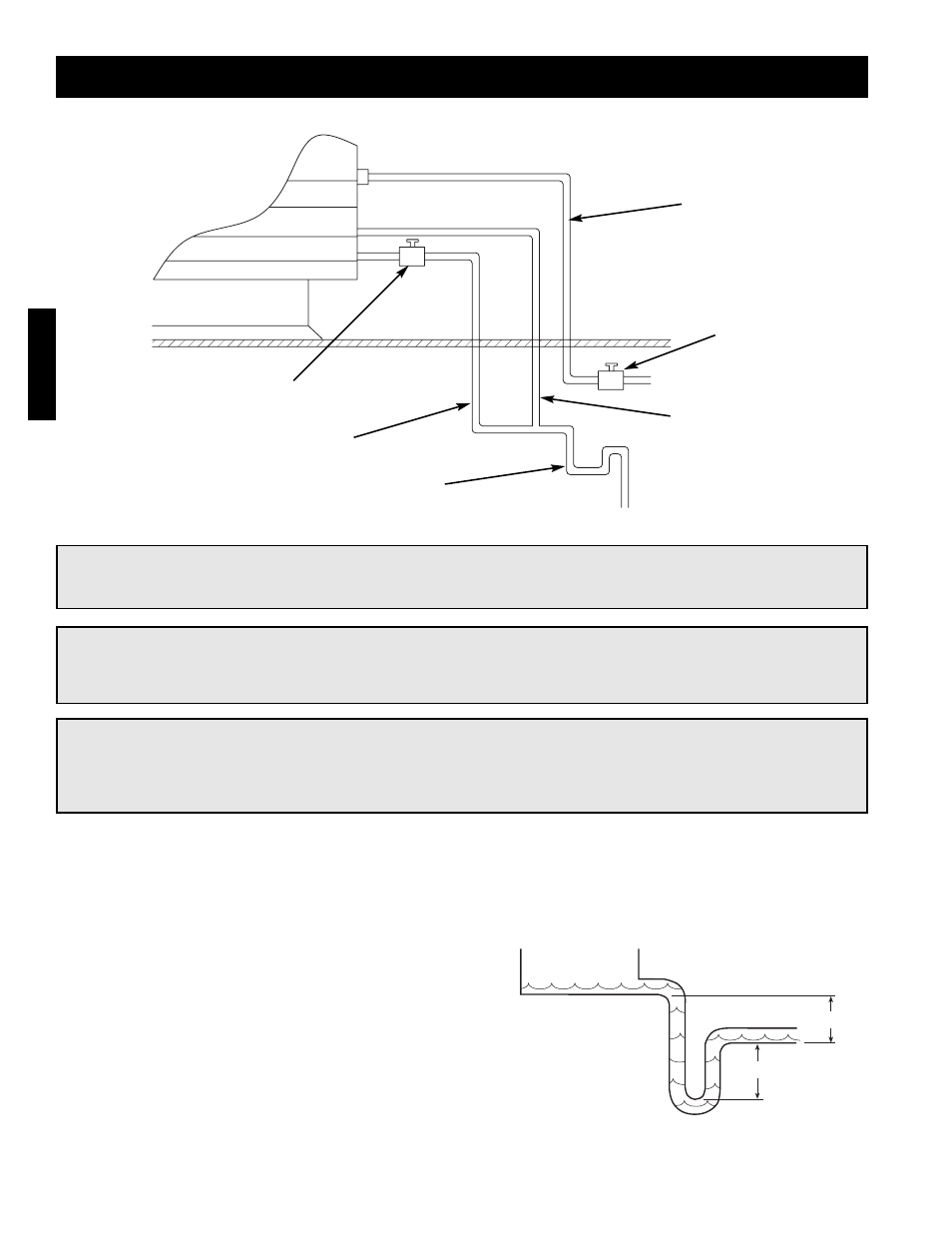
Installation - Evaporative Cooler Piping (Optional)
Evaporative Cooling with Recirculating Pump
Installation
IMPORTANT!
The supply line should be of adequate size and pressure to resupply the amount of water lost due to
bleed-off and evaporation. The drain line should be the same size or larger than the supply line.
Step 1 Install the Water Supply Line
Supply line opening requirements vary by unit size and arrangement and are field supplied. Connect the water
supply line to the float valve through the supply line opening in the evaporative cooling unit. Install a manual
shutoff valve in the supply line as shown above.
Step 2 Install the Drain Line
Connect an unobstructed drain line to the drain and
overflow connections on the evaporative cooler. A manual
shut off valve (by others) is required for the evaporative
cooler drain line. A trap should be used to prevent sewer
gas from being drawn into the unit. Refer to piping
diagram above.
Step 3 Check/Adjust Water Level
Check the water level in the sump tank. The water level
should be above the pump intake and below the overflow.
Adjust the float as needed to achieve the proper water
level.
CAUTION!
Provisions must be taken to prevent damage to the evaporative cooling section during freezing
conditions. The sump, drain lines and supply lines must be drained prior to freezing conditions or an
alternate method must be used to protect the lines and media.
IMPORTANT!
All supply solenoids, valves and all traps must be below the roofline or be otherwise protected from
freezing.
6 in. min.
6 in. min.
Supply Line
Overflow
Trap
Drain Line Valve
(Normally Open)
Drain Line
Supply Line Valve
(Normally Closed)
Recirculating Evaporative Piping
Drain Trap