Reference – Greenheck DG / DGX with Pilot Ignition (463555 IOM) (Pre-2008) User Manual
Page 47
47
Reference
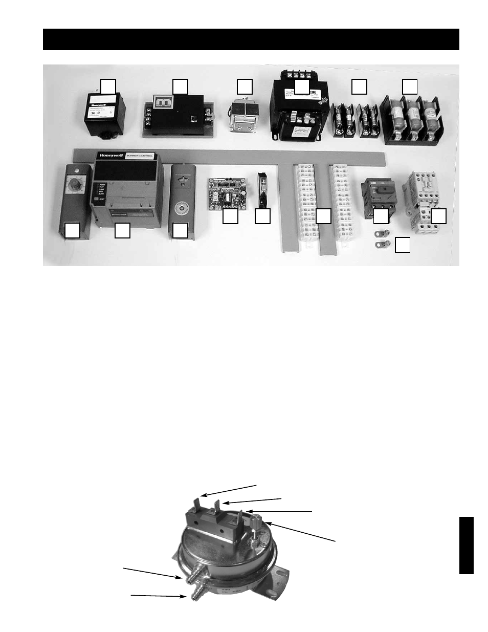
1.
Heating/Cooling Inlet Air Sensor (Optional) - Ductstat that automatically de-energizes burner when inlet air
temperature rises above set point, or shuts down cooling when temperature falls below set point.
2.
Flame Safeguard - Monitors flame, shuts-down unit when unsafe conditions are detected.
3.
High Limit - Prevents unit from discharging air above a set point.
4.
Building Freeze Protection (Optional) - Prevents unit from discharging air below a set point after a time
delay.
5.
Heat/Cool Relay - Allows power to pass to Flame Safeguard or cooling unit.
6.
Terminal Strip - 24 Volt power strip for control wiring.
7.
Main Disconnect - On/Off switch, provides single point power connection to unit.
8.
Grounding Lugs - Completes electrical circuit
9.
Motor Starters - 24 Volt magnetic contacts for starting motors, comes standard with electronic overload,
may be provided with auxiliary contacts.
10.
Spark Generator - Causes the spark rod to spark and ignite the flame.
11.
Amplifier - Controls modulating valve, assures the desired temperature is delivered.
12.
Low Voltage Transformer - Reduces voltage to the Maxitrol system.
13.
Transformers - multiple transformers provide appropriate voltage to controls, blowers, etc.
14.
Secondary fuses - Provides proper fusing for all electrical components other than the motors.
15.
Motor Fuses - Provides proper fusing for supply and exhaust fan motor(s).
12
10
11
1
5
4
3
2
14
6
8
7
9
15
13
Typical Control Center Layout
Reference
Dirty Filter Switch
Negative Pressure
after the filters
Common
Normally Open
Normally Closed
CCW to Decrease Trip Point
CW to Increase Trip Point
Positive Pressure
before the filters