Analog input confi guration screen, Lead/lag controller technical guide 14, Confi guring analog inputs – Orion System Lead Controller User Manual
Page 14
Section 4: Confi guring Analog Inputs
Lead/Lag Controller Technical Guide
14
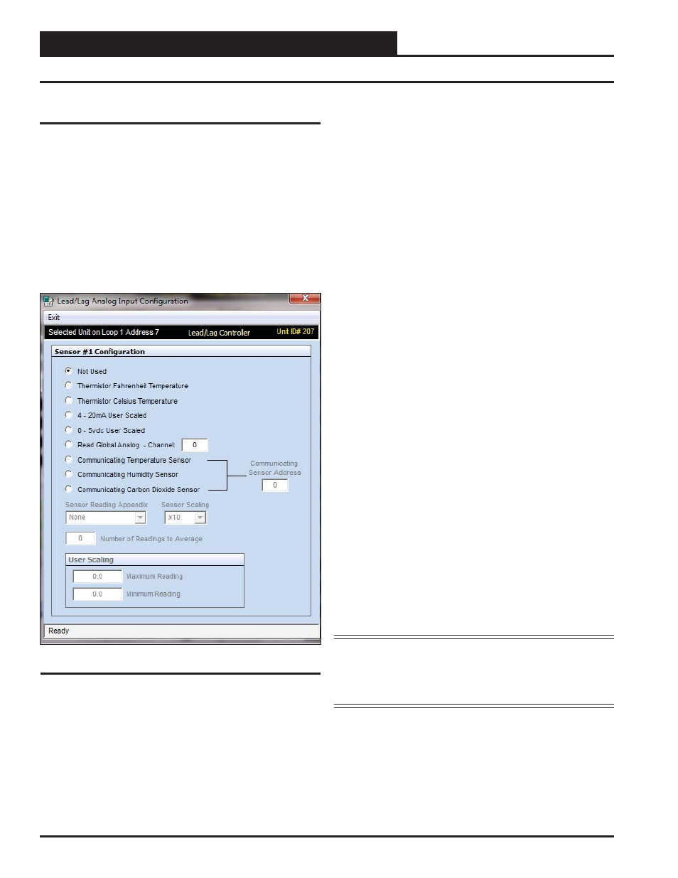
Analog Input Confi guration Screen
Confi guring Analog Inputs
Left-click in the data entry fi eld in the Analog Inputs Window to open
the Analog Input Confi guration Window (Figure 12).
The eight analog inputs can be confi gured in several different ways.
Generally, the fi rst four inputs are the only ones used for Lead/Lag
control. These inputs can be used to generate an alarm and switch
from one device to another if the fi rst cannot maintain a temperature
or PSI setpoint. The others can be used to monitor various inputs.
The controlling devices can be set up to look at one sensor or each
device can have its own sensor.
The following confi gurations are available for each Analog Input:
● Not Used
● Thermistor Fahrenheit Temperature: 10K Ohm Type III
Scaled for Fahrenheit. Set jumper to the appropriate setting
(see Figure 2, page 6).
● Thermistor Celsius Temperature: 10K Ohm Type III
Scaled for Celsius. Set jumper to the appropriate setting (see
Figure 2, page 6).
● 4 - 20mA User Scaled: 4-20mA User-Scaled Sensor. Set
jumper to the appropriate setting (see Figure 2, page 6).
● 0 - 5vdc User Scaled: Select this option if using a 0-5vdc
scaled sensor. Set jumper associated with this input to the
appropriate 0-5v setting (see Figure 2, page 6.)
● Read Global Analog Broadcast Channel from Another
Controller
● Communicating Temperature Sensor ( OE217-02):
If using a WattMaster Communicating Temperature
Sensor with a modular cable, confi gure this input to read
the appropriate Communicating Sensor Address. Enter
an address from 1-8 in the < Communicating Sensor
Address>
fi eld and press
<ENTER>
.
● Communicating Humidity Sensor ( OE217-03): If using
a combination Temperature and Humidity Communicating
Sensor with a modular cable, confi gure one input to read
the temperature and another input to read the humidity,
both using the same Communicating Sensor address. Enter
an address from 1-8 in the <Communicating Sensor
Address>
fi eld and press
<ENTER>
.*
● Communicating Carbon Dioxide Sensor ( OE256-05
or OE256-07)
: If using a WattMaster Communicating CO
2
Sensor with a modular cable, confi gure this input to read
the appropriate Communicating Sensor Address. Enter
an address from 1-8 in the <Communicating Sensor
Address>
fi eld and press
<ENTER>
.*
*NOTE: See the E-BUS Digital Room Sensor Technical Guide,
E-BUS Wall-Mounted CO
2
Sensor Technical Guide,
or E-BUS Duct-Mounted CO
2
Sensor Technical Guide
for information on how to address the communicat-
ing sensors.
Figure 12: Analog Input Confi guration Window