Confi guring alarms, Lead/lag controller technical guide 36, Alarm notifi cation – Orion System Lead Controller User Manual
Page 36: Confi guring and enabling alarms
Section 10: Confi guring Alarms
Lead/Lag Controller Technical Guide
36
Confi guring Alarms
Alarm Notifi cation
The controller can generate alarms for remote alarm notifi cation if
alarms have been enabled and if Prism 2 is connected and running
24 hours a day. If an alarm condition occurs, the
<ALARM>
button in
the upper right hand corner of the Lead/Lag Controller Status Screen
will light up. See Figure 66. If no alarm(s) exists, the button will be
gray and display the words, No Alarms. See
Figure 67.
Figure 67: No Alarms Button
Individual alarms will also be indicated with a bright red alarm bell
icon in the Relays Status Window. See Figure 68.
Figure 68: Relay Status Alarm Icon
Alarm
Indicator
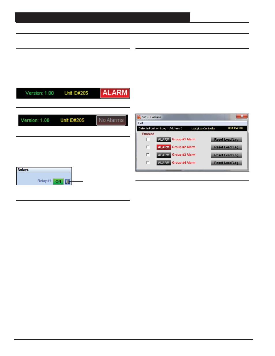
Confi guring and Enabling Alarms
Alarms are enabled in the Lead/Lag Alarms Window.
To confi g-
ure alarms, click on the
<ALARM>
or
<No Alarms>
button in the
upper right hand corner of the Lead/Lag Controller Status Screens
(Figures 8 & 9 , pages 11 & 12). The Lead/Lag Alarms Window
will open. See Figure 69.
Due to the quantity of Inputs and Outputs on the Lead/Lag controller,
alarms have been grouped into 4 Groups. Each group corresponds
to a Schedule. So Group #1 is linked to Schedule #1, Group #2 to
Schedule #2, and so on.
Figure 66: ALARM Button
Figure 69: Lead/Lag Alarms Window
Click the Enabled box beside any Alarm you wish to enable. When
that alarm condition occurs, the
<ALARM>
button in the upper right
corner of the Main Prism 2 Screen will turn bright red (Figure 6,
page 10 & Figures 8 & 9, pages 11-12). This selection will also
allow that Alarm to send out an e-mail notifi cation if your system
is set up for that function. See the Prism 2 Technical Guide for
instructions on setting up e-mail alarm notifi cations.
If the proof source doesn’t meet the requirements in the programmed
amount of time, the system switches to the standby output and gener-
ates the proof alarm and either the Lead or Standby alarm, depending
on which relay caused the condition.
If only one Group generates an alarm, normal operation can be
restored by clicking the
< Reset Lead/Lag>
button. Clicking the
<Reset Lead/Lag>
button will restart the system using the relay
with the least amount of accumulated run time. Both do not have
to be in an alarm state for you to reset the lead/lag operation. If the
system has switched to the standby output, it can be restored to the
lead output if you want to test it again or repairs have been made
and you just want to restore normal operations.
If more than one Group generates an alarm, they will not attempt to
activate again until the
<Reset Lead/Lag>
button has been clicked.
This is to protect the equipment from possible severe damage if an
output is attempting to operate damaged equipment.