Orion System Lead Controller User Manual
Page 28
Section 7: Confi guring Analog Outputs
Lead/Lag Controller Technical Guide
28
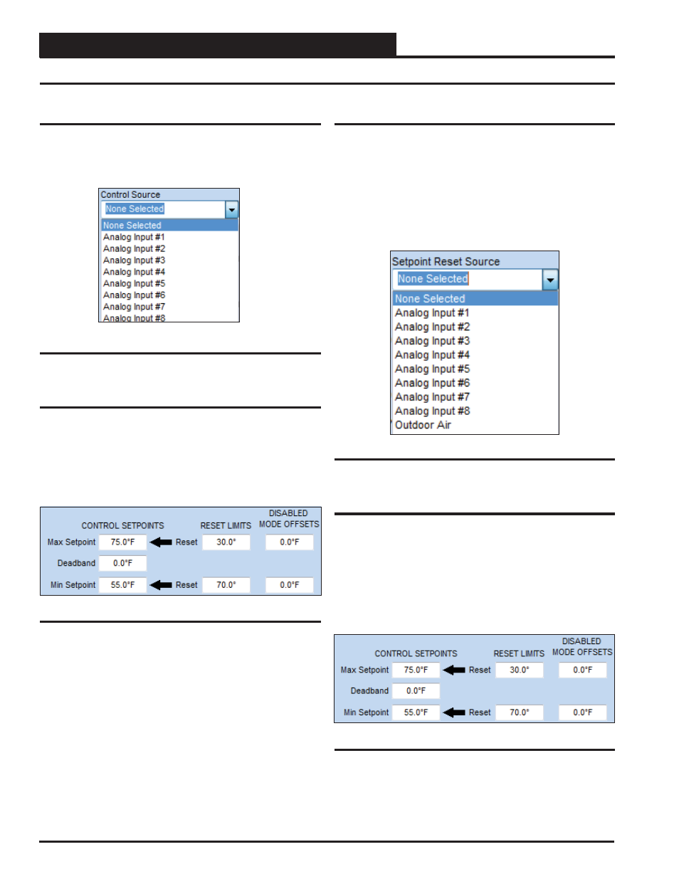
Control Source
The Control Source Options are as follows (Figure 43):
● Analog Inputs #1 - 8
Control Source, Control Setpoints, Setpoint Reset Source
Figure 43: Control Source
Control Setpoints & Reset Limits
For most applications, only the Max Setpoint and the Deadband will
be used. See Figure 44. Unless a Setpoint Reset Source is selected,
the other values in this section will be grayed-out and not used. In
this situation, the Max Setpoint will be the setpoint you are trying to
maintain. The Deadband is the range above and below the Setpoint
in which no control signal change is made.
Figure 44: Control Setpoints & Reset Limits
Setpoint Reset Source
You can confi gure a Setpoint Reset Source that will allow reset of the
Control Setpoints (Figure 45). Once a Reset Source is selected, you
will be able to confi gure both a “Max Setpoint” and a “Min Setpoint”
as well as a Max Reset value and a Min Reset value (Figure 46).
As the Reset Source value varies between the Max and Min Reset
values, the Control Setpoint will be proportionally reset between
the Max and Min Control Setpoints. At the Max Reset value, the
Control Source will be at the Max Setpoint, regardless if it is an
inverse relationship.
Figure 45: Setpoint Reset Source
Disabled Mode Offsets
The Disabled Mode Offsets (Figure 46) can be used if you are
using an Enabling Relay, an Enabling Binary Input, or a Control-
ling Schedule. Anytime this output is not enabled by the Enabling
Relay or the Enabling Binary, or is in the Unoccupied Mode (per the
Schedule), these offsets will be applied to the Max/Min Setpoints
to initiate the control operation of this analog output. These would
then act as “Night Setback” type offsets. If these offset values are
‘0’, there will be no Disabled Mode operation.
Figure 46: Disabled Mode Offsets