Alternate override and override – Orion System Lead Controller User Manual
Page 30
Section 7: Confi guring Analog Outputs
Lead/Lag Controller Technical Guide
30
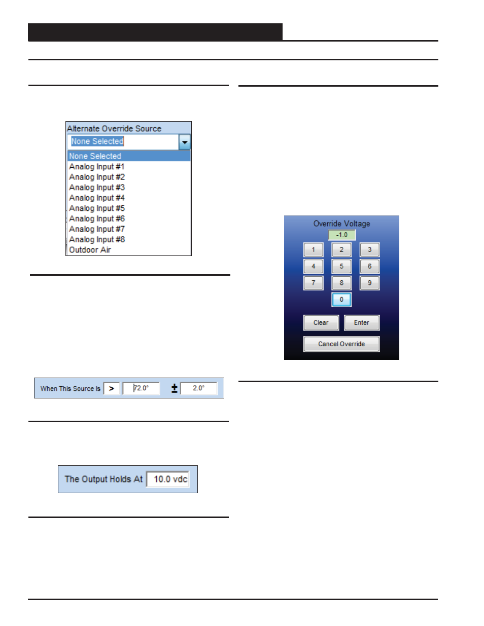
Alternate Override and Override
Alternate Override
An Alternate Override Source can be selected to override the output
signal of this Analog Output to a fi xed value when a certain condi-
tion occurs (Figure 52).
First select which Override Source to use:
● Analog Inputs # 1 – 8
● Outdoor Air
Next select the logic, setpoint, and deadband that will determine
the Override (Figure 53). Right or left-click in the Logic Field to
select
<
,
>
, or
=
.
Figure 52: Alternate Override
Figure 53: Logic, Setpoint, and Deadband
Figure 54: Voltage
Override & Cancel Override
You can manually override the logic of an Analog Output and force
it to a specifi c voltage. The Override Voltage fi eld defaults to “-1.0”
which means no override.
Right-click in the data entry fi eld in the Analog Outputs Window
(Figure 37, page 25) to open the Override Voltage Box shown in
Figure 55 and enter an override value. Click the
<Enter>
button to
save the value. If you enter an incorrect value, click the
<Clear>
but-
ton to start over. If there is any value in the fi eld, including “0” when
you click
<Enter>
, the voltage from this output will be forced to that
value. Canceling the Override will cause the voltage to go back to its
original reading, and the Override Voltage fi eld will display “-1.0”.
Figure 55: Calibrate and Override Sensor
Finally, select the voltage you want to hold this output to based on
the above logic (Figure 54).