Increasing and decreasing proof setpoints – Orion System Lead Controller User Manual
Page 23
Lead/Lag Controller Technical Guide
Section 6: Confi guring Relays
23
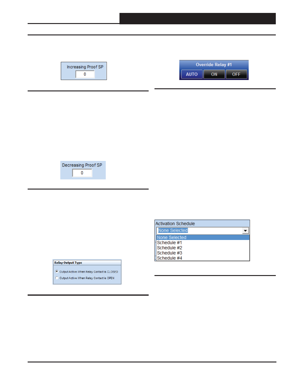
Increasing and Decreasing Proof Setpoints
Figure 30: Increasing Proof Setpoint
Use this option if you want to use a temperature as proof that the
device is operating correctly and to determine if the unit has failed
if it cannot maintain a temperature that is above this setpoint. For
example, if the unit is trying to maintain a 80° supply air temperature
and drops below this setpoint for the “ Proof Failure Timeout Delay”,
then the Lead/Lag controller will shut off the device that is running,
start the backup device, and generate an alarm.
Increasing Proof Setpoint
Figure 31: Decreasing Proof Setpoint
Use this option if you want to use a temperature as proof that the
device is operating correctly and to determine if the unit has failed
if it cannot maintain a temperature that is below this setpoint. For
example, if the unit is trying to maintain a 55° supply air temperature
and it rises above this setpoint for the “Proof Failure Timeout Delay”,
then the Lead/Lag controller will shut off the device that is running,
start the backup device, and generate an alarm.
Decreasing Proof Setpoint
Figure 32: Relay Output Type
Some control methods require the relay contacts to be closed when
the output is activated; others require the contacts to be open. You
can select which method of control to use with this option.
Relay Output Type
Figure 33: Relay Override
In order to override the relays on, off, or put them back in auto mode,
right-click on the relay’s On/Off box in the Relay Confi guration
Window. See Figures 23 & 24, page 19.
Relay Override
Activation Schedule
Control of the Lead/Lag devices must be initiated based on a
Schedule and/or a Binary Input Activation. If only an Activation
Schedule is selected the Lead/Lag operation will be active whenever
the Schedule is Occupied. The schedule can be set with a 7-day
schedule with 2 start/stops per day, or it can be confi gured for con-
tinuous 24/7 operation. If both an Activation Schedule and a Binary
Input Activation are selected, the Lead/Lag operation will be active
when the Binary Input is active and the Schedule is Occupied. If no
Activation Schedule is selected, the Lead/Lag operation will activate
solely on the basis of a Binary Input Activation.
The controller only uses Schedule #1 for control of 2 Lead/ 1 Lag
functions. For Lead/Lag operation, 4 schedules are available. Sched-
ule #1 would correspond to Lead/Lag #1 operation, Schedule #2 for
Lead/Lag #2 operation, etc. See Section 9: Setting Schedules, page
32 for more information.
Figure 34: Activation Schedule