Binary input activation and timers – Orion System Lead Controller User Manual
Page 24
Section 6: Confi guring Relays
Lead/Lag Controller Technical Guide
24
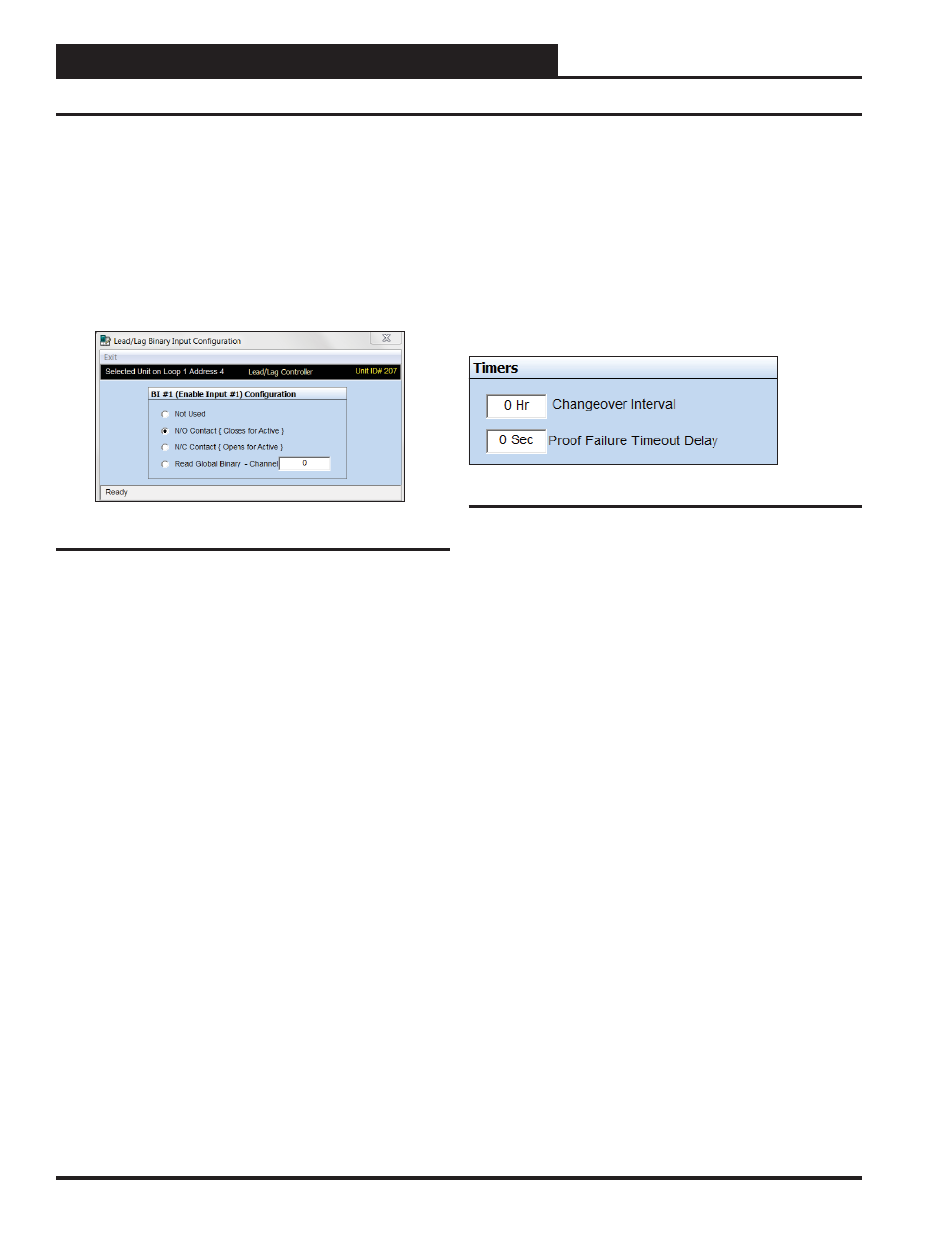
Timers
The Changeover Interval is the amount of time the fi rst device will
run before it switches to a backup device. See Figure 36. It can be
set up to a maximum of 1488 hours.
The Proof Failure Timeout Delay establishes the time the controller
will wait to prove that the Lead device is running correctly before
switching to Lag device and generating an alarm. If it is a pump, it
could be proof of water fl ow or pressure, and if it is an air handling
unit, it might be temperature or proof of air fl ow. See Figure 36.
Figure 36: Timers Window
Binary Input Activation (Enable)
Control of the Lead/Lag devices must be initiated based on a Binary
Input Activation (Enable) and/or an Activation Schedule. Binary
Inputs #1 - #4 are used as Activation Binary Inputs. If no Activation
Schedule is confi gured, the Lead/Lag operation will be initiated
solely on the basis of a Binary Input Activation. If both a Binary
Input Activation and an Activation Schedule and are selected, the
Lead/Lag operation will be active when the Binary Input is active
and the Schedule is Occupied.
Figure 35: Binary Input Activation Window
Binary Input Activation and Timers