Appendix a - sample confi gurations – Orion System Lead Controller User Manual
Page 46
Appendix A - Sample Confi gurations
Lead/Lag Controller Technical Guide
46
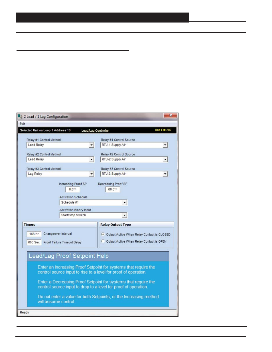
2 Lead/1 Lag Example - Controlling 3 Roof Top Units
Figure 85: Relay Confi guration
Relay Confi guration
Relays 1 & 2 are confi gured as Lead relays and Relay 3 is confi gured
as a Lag relay. The control source is the supply air temperature for
each unit. The Decreasing Proof Setpoint is set to 60°F, meaning that
if the supply air temperature of any of the units running drops below
the setpoint for 10 minutes, that unit will be shut off and the unit not
running will be started. See Figure 85 for Relay 1’s confi guration.
This relay (Figure 85) was chosen to be the Lead control output and
was connected to AHU #1. Either RTU could have been selected as
RTU #1. This was an arbitrary decision.
The Supply Air was selected as the Control Source and the Proof
Setpoint was set to 60.0°F. The RTU’s will change the Lead every
168 Hours, and if the Supply Air rises above 60°F for more than
10 minutes, it will be considered to be in failure mode and the Lag
RTU will be activated. Also, an alarm will be generated so that an
immediate service call can be made to determine the cause of failure.
If both units should happen to fail, there is no further redundant
capabilities, and service personnel will need to correct the problems
and then Reset the control from the Alarm Indicator Screen.