Operator interfaces technical guide 11 – Orion System VCM User Manual
Page 11
Operator Interfaces
Technical Guide
11
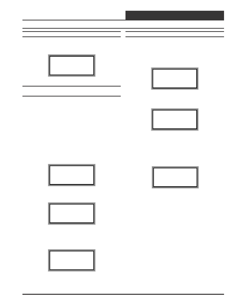
Modular Service Tool Initialization Screen
After connecting the Service Tool to the controller with the supplied
cable, press the “On” key. The following screen will appear.
Service Tool vX.XX
Monday Operations
09/09/02 04:26 PM
Stand Alone Mode
Configuring The Modular Service Tool For
Network Or Stand-Alone Operation
As with the System Manager described previously, you must determine
if the mode displayed is correct for your system. If it is configured for
Stand Alone you will see the words “Stand Alone Mode” on the bot-
tom line of the display. This is the factory default setting. If you are
using this tool on a system or controller that does not have a CommLink
or MiniLink PD installed, then this is the correct setting and you can
proceed to desired screen by pressing the menu key or any function key.
If you are using this Service Tool on a communications loop and have
installed a MiniLink PD or CommLink II communications interface,
then you need to operate in network mode and the bottom line should
display the words “Network Mode”.
If your display indicates a different mode than the one you need, press
the "Enter" key and the following screen will appear.
1) Set Time & Date
2) Communications
3) Energy Saving
ESC) Exit Menu
Press the “2” key on the keypad to enter the communications screen.
0) Stand Alone
1) Network System
Enter Mode Of Op:.xx
As the screen indicates, press the right or left arrow keys to select the
proper mode of operation. When you are finished press “Enter” to
move back to the main menu screen.
You Have Changed The
System Mode
Press Any Key To
Continue
Modular Service Tool Alarm Search
First, press the “Alarm” key. The Unit Selection screen below will be
displayed. Enter the Unit ID of any controller on the system and press
“Enter”. This is the unit ID of the loop where the alarm search will be
done. Unlike the System Manager, only the alarms on this loop will be
searched, not the entire system.
Unit Selection
Enter Unit ID#
Selected ID#: xxxx
The following screen will appear. The Modular Service Tool will search
for any active alarms on the local loop.
Alarm Screen
SEARCHING!
After the Modular Service Tool completes it’s search, it will list the first
unit on the local loop, whose ID was entered, that currently has an
active alarm. Press “Enter” to scroll through all the alarms for control-
lers on that particular loop. To move to the next controller or back to the
previous unit use the “Prev” or “Next” arrows to move between con-
trollers with alarms on the loop.
Alarm Search Screen
Loop = 1 Unit = 59
Space Sensor Failure
To clear any alarms that are found you must fix the problem indicated in
the alarm. Once the problem is fixed, the alarm will clear from the screen
the next time the unit is polled.