Programming the vcm controller – Orion System VCM User Manual
Page 22
Technical Guide
Operator Interfaces
22
Configuration Screen #39
VCM Cnfg ID 59
Enable Broadcast To
Multiple Loops: NO
[0=NO 1=YES]
When “1=YES” is selected, all broadcasts that have been configured on
Configuration Screens 31 through 35 will be sent to all local loops on
the entire system, not just the local loop the VCM controller is on. This
is normally only required if you have a large HVAC unit that requires
more than the 58 VAV/Zone controllers normally allowed on the local
loop. This allows other VAV/Zone controllers connected on additional
local loops to receive the required broadcasts. This only is allowed when
you have a single VCM controller with VAV/Zone controllers on mul-
tiple loops. Other VCM or add-on devices may be connected but no
other VCM with VAV/Zone controllers can be connected on the sys-
tem.
Configuration Screen #40-43
VCM Cnfg ID 59
Cooling Stage Delays
Staging Up...: 3 Min
Staging Down : 1 Min
VCM Cnfg ID 59
Cooling Stage Delays
Min Run Time: 5 Min
Min Off Time: 3 Min
VCM Cnfg ID 59
Heating Stage Delays
Staging Up...: 3 Min
Staging Down : 1 Min
VCM Cnfg ID 59
Heating Stage Delays
Min Run Time: 2 Min
Min Off Time: 1 Min
Both the Heating Stages and the DX Cooling Stages utilize Staging Up
and Down Delay Periods between stages and Minimum Run Times
and Off Times.
Both modes have their own set of Staging and Run Delay Times. The
Heating Timer Screens look exactly the same as the Cooling Timer
Screens except they reference the Heating settings instead of the Cool-
ing settings.
See the Sequence of Operation Manual for information on how these
Delays and Run Times are used.
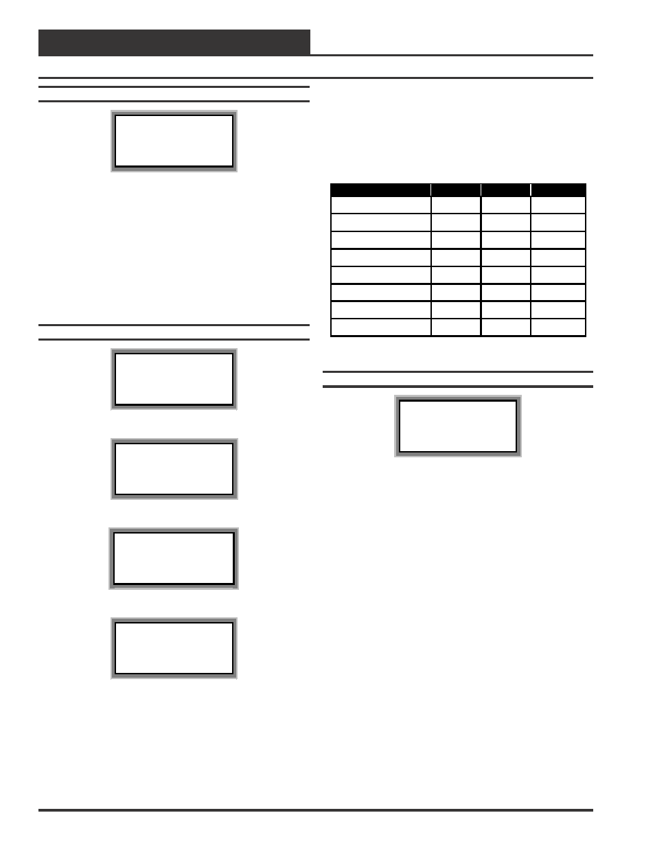
Description
Minimum
Default
Maximum
Cooling Stage Up
3 Min
3 Min
15 Min
Cooling Stage Down
1 Min
1 Min
15 Min
Cooling Min Run Time
5 Min
5 Min
15 Min
Cooling Min Off Time
3 Min
3 Min
15 Min
Heating Stage Up
3 Min
3 Min
15 Min
Heating Stage Down
1 Min
1 Min
15 Min
Heating Min Run Time
2 Min
2 Min
15 Min
Heating Min Off Time
1 Min
1 Min
15 Min
Configuration Screen #44-68
VCM Cnfg ID 59
Relay Configurations
Rly xx: Not Used
Press “0” To Change
Relay #1 is not configurable as it is reserved for the Supply Air Fan.
Relays #2-#21 are configurable for the following options:
•
Cooling Stage
•
Heating Stage
•
Warm-up Mode
•
Reversing Valve
•
Reheat
•
Pre-Heater
•
Exhaust Fan
•
Alarm
•
Override
•
Occupied
•
Economizer
Relays #2 through #21 can be individually configured. By using all (4)
of the available 4 Relay Expansion Boards and the 4 relay outputs avail-
able on the VCM controller, you have the ability to configure up to a
combined total of 20, Heating Stages, Cooling Stages, and options 3
through 11 listed above. Only the Heating and Cooling relays can be
configured with multiple outputs. If any other option is selected more
than once, it will simply activate redundant relays but no multiple stag-
ing will occur.
Programming The VCM Controller