Programming the vcm controller – Orion System VCM User Manual
Page 34
Technical Guide
Operator Interfaces
34
Programming The VCM Controller
Caution: The Damper Force Modes should only be used by quali-
fied service personnel. Serious damage to the ductwork
could result if the dampers are all forced closed and
the HVAC unit fan is operating.
Outputs Force
Output Force settings are available for testing or troubleshooting the
system. These Force settings can only be accessed and programmed
from the Modular Service Tool, the System Manager does not allow for
programming of this function.
Caution: The Output Force settings should only be applied by
qualified service personnel. Serious damage to the
HVAC unit could result from improper use of these
Outputs Force settings.
To access the Output Force settings simply press the “Balance-Test”
key on the Modular Service Tool. You will then see the unit ID screen.
Enter the unit ID of the VCM controller you wish to access and press
"Enter". The Output Force settings are only available for the VCM con-
troller. They are not supported for the VAV/Zone controllers or other
Add-on controllers. If you enter a unit ID for any other type of unit
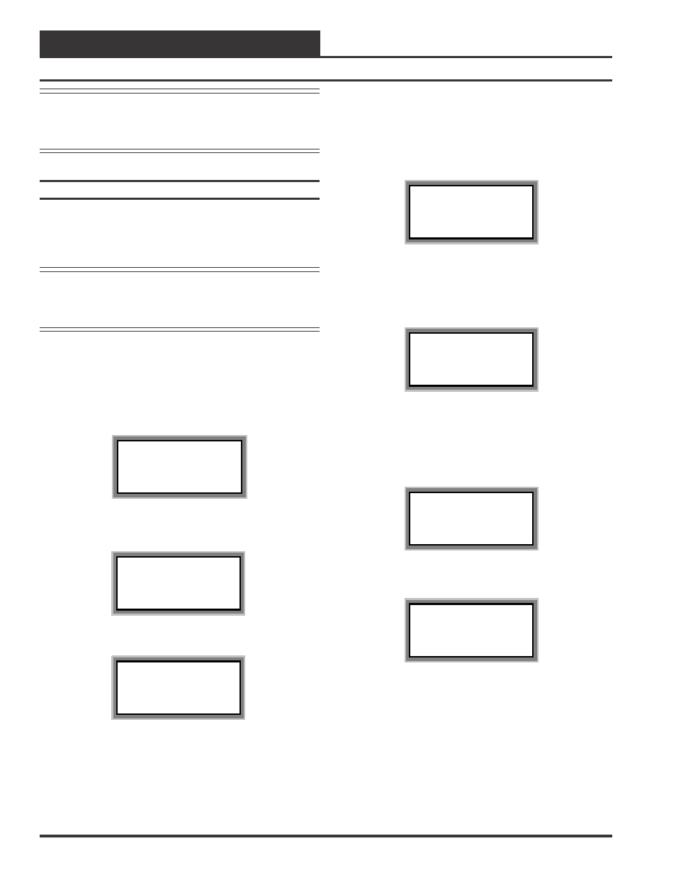
except a VCM controller the following screen will be displayed.
Unit xxx Does Not
Support The Function
Press Any Key To
Continue
If you entered the unit ID of a VCM controller the following screen will
be displayed.
1)Outputs Force
2)Dampers Force
Press the “1” key to access the Outputs Force screen.
Supply Fan Override
Enter Override...: 0
[0=Auto 1=ON 2=OFF]
The first Outputs Force screen allows the AHU fan relay to be set for
Auto, ON or OFF by entering a 0, 1 or 2 as desired. The default setting
is 0=Auto. After completion of all troubleshooting or testing proce-
dures all relays should be changed back to this setting. The 1=ON set-
ting will force the relay to the ON (energized) position. The 2=OFF
selection will force the relay to the OFF (de-energized) position.
The next screen displays the Relay Overrides for Relay 2. After press-
ing the "Enter" key the next relay will be displayed. All 20 Relay Over-
ride screens (including the AHU fan relay) are available by pressing the
"Enter" key after each setting is made.
Relay Overrides
Relay 2 Override: 0
[0=Auto 1=ON 2=OFF]
After the screen for relay 21 is displayed, the first Analog Output Over-
ride screen will be displayed.
Analog Output 1 Screen
Economizer Overrides
Analog Output #1
Override Volts: -1.0
[-1.0=Auto]
The default setting for normal operation is -1.0 volts. Voltages between
0 to 10.0 can be set for any of the Analog Output Overrides. Press
“Enter” after making a setting change and the next Analog Output Over-
ride screen will be displayed.
Analog Output 2 Screen
Supply VFD Override
Analog Output #2
Override Volts: -1.0
[-1.0=Auto]
Analog Output 3 Screen
Exhaust VFD Override
Analog Output #3
Override Volts: -1.0
[-1.0=Auto]