Programming the vav/zone controller, Technical guide operator interfaces 44 – Orion System VCM User Manual
Page 44
Technical Guide
Operator Interfaces
44
Programming The VAV/Zone Controller
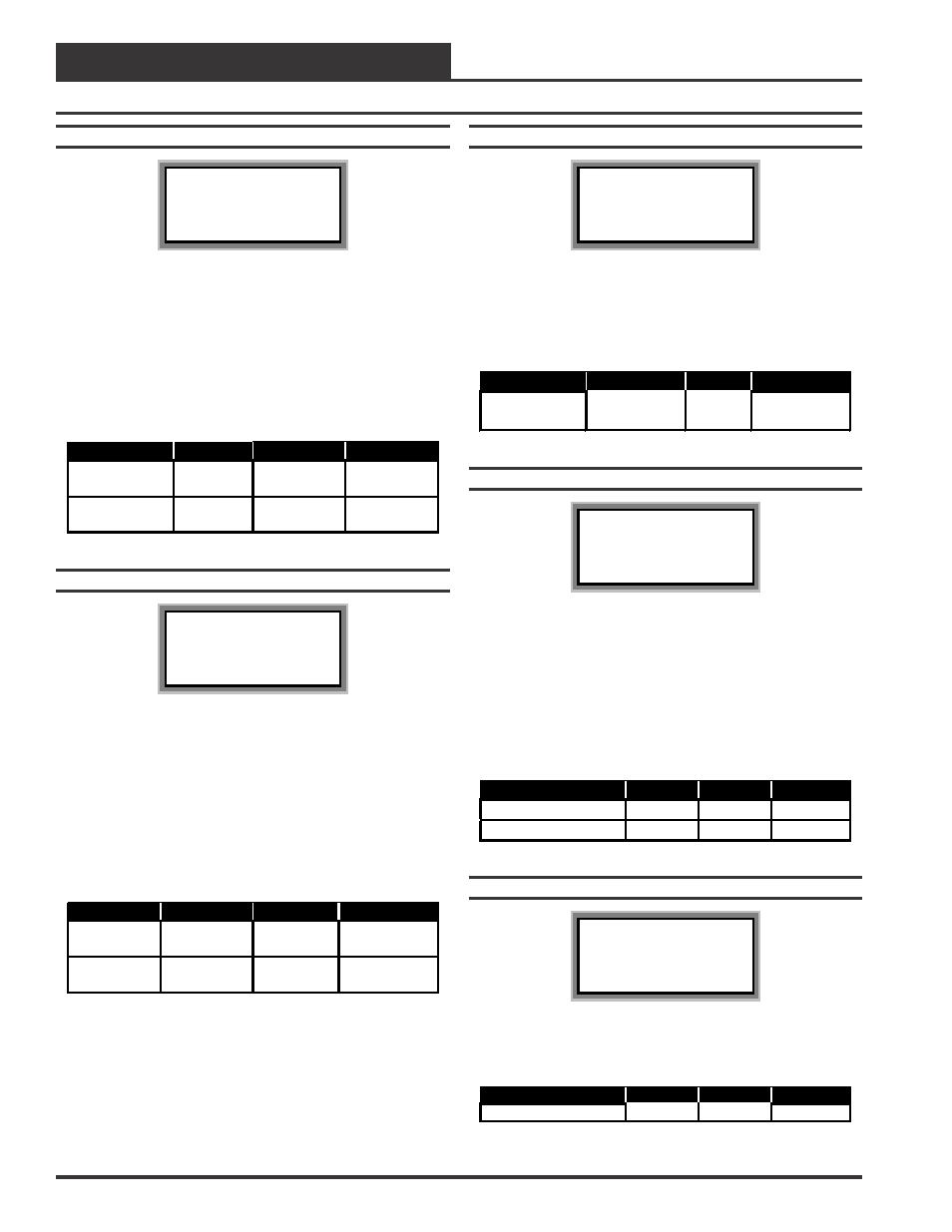
Setpoint Screen #6
HC Box Spts IDxxxx
Damper/Airflow Spt
Cool Min.: xxx %
Heat Min.: xxx %
During Supply Air Cooling Mode if the space being served by this
damper is satisfied and has no cooling demand the damper will close to
this Cool Min setting. This provides a minimum amount of airflow
into the space for ventilation, even if the space does not require addi-
tional cooling. During Supply Air Heating Mode if the space being served
by this damper is satisfied and has no heating demand the damper will
close to this Heat Min setting. This provides a minimum amount of
airflow into the space for ventilation, even if the space does not require
additional heating.
Description
Minimum
Default
Maximum
Cool Min
0% or
0 CFM
10% or
100 CFM
100% or
30000 CFM
Heat Min
0% or
0 CFM
10% or
100 CFM
100% or
30000 CFM
Setpoint Screen #7
HC Box Spts IDxxxx
Damper/Airflow Spt
Nt/Rh Min.: xxx %
Fan On Min: xxx %
The Nt/Rh Min is the position the damper will move to when the sys-
tem is in Override Mode and this particular damper is not part of the
override group. This Nt/Rh Min position only affects non-fan powered
boxes..
The Fan On Min is used for Parallel Fan boxes only. This is the damper
position that will cause the Parallel Fan to start if the damper/airflow
drops below this value. Normally the Parallel Fan only operates when
the Reheat stages are activated. If this is not a Parallel Fan box, the last
line will remain blank. Series Fan boxes are not affected by this setting
as the fan is always on anytime the HVAC unit fan is running.
Description
Minimum
Default
Maximum
Nt/Rh Min
0% or
0 CFM
0% or
0 CFM
100% or
30000 CFM
Fan On Min
0% or
0 CFM
0% or
250 CFM
100% or
30000 CFM
Setpoint Screen #8
HC Box Spts IDxxxx
Damper/Airflow Spt
Fixed Pos: xxx %
Many times while troubleshooting a system, it is useful to have the
zone damper set to a specific damper position or airflow setting. This
setpoint can be used to determine where the damper/airflow will re-
main when the box controller receives a Force to Fixed Position com-
mand from the user.
Description
Minimum
Default
Maximum
Fixed Pos
0% or
0 CFM
0% or
0 CFM
100% or 30000
CFM
Setpoint Screen #9
HC Box Spts IDxxxx
Zone Alarm Offsets
Hi Zone......: xx
°
F
Lo Zone......: xx
°
F
The VAV Box Controller can be setup to generate an alarm anytime
the Zone Temperature exceeds the user defined alarm limits for a user
defined period of time. A High Temperature Alarm Setpoint is created
by adding the Hi Zone Alarm offset to the current Cooling Setpoint.
The Low Temperature Alarm Setpoint is created by adding the Lo Zone
Alarm offset to the current Heating Setpoint. If the zone temperature
exceeds either of these limits for a period defined by the Alarm Delay
setpoint, the controller can generate an alarm callout if all the options
required for this to occur are installed.
Description
Minimum
Default
Maximum
Hi Zone Alarm
+1
°
F
+30
°
F
+50
°
F
Lo Zone Alarm
-1
°
F
-30
°
F
-50
°
F
Setpoint Screen #10
HC Box Spts IDxxxx
Zone Alarm Delay
Must Be Out Of
Limits For.: xxx Min
As mentioned above, if the user configures the controller to generate
zone temperature alarms, this is the amount of time the temperature
must be outside the alarm limits before an alarm is generated.
Description
Minimum
Default
Maximum
Out Of Limits
1 Min
30 Min
300 Min