Operator interfaces technical guide 27 – Orion System VCM User Manual
Page 27
Operator Interfaces
Technical Guide
27
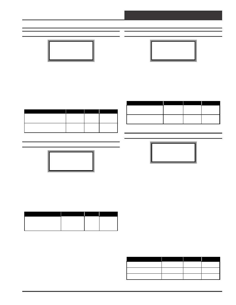
Setpoint Screen #16
VCM Spts ID 59
CO2 Protection Limit
Max Level..: 900 PPM
Reset Rnge.: 100 PPM
When the CO
2
level rises above the CO
2
Protection Limit Max Level,
the Economizer’s Minimum Position will begin to reset open propor-
tionally between the CO
2
Protection Limit Max Level Setpoint and the
Reset Range Setpoint. The Reset Range value is added to the Max Level
value. If the CO
2
levels are equal to or above the Max Level plus the
Reset Range, the Economizer will be opened to its Maximum Econo-
mizer Position if high CO
2
levels occur.
Description
Minimum
Default
Maximum
CO2 Protection Limit
Max Level
0 PPM
900 PPM
3000 PPM
CO2 Protection Limit
Reset Rnge
0 PPM
100 PPM
1500 PPM
Setpoint Screen #17
VCM Spts ID 59
Static Spt...: 0.50”
Deadband.....: 0.10”
Control Rate.: 10 s
For VAV units, a Supply Fan VFD or a Bypass Damper Actuator is
used to maintain the Duct Static Pressure Setpoint. The Static Pressure
Output Signal varies to control the Static Pressure Setpoint. If the Duct
Static Pressure is above the Static Setpoint plus the Deadband, the Static
Pressure Output Signal will be reduced at every Control Rate interval.
If the Static Pressure is below the Static Setpoint minus the Deadband,
the Output signal will be increased at every Control Rate interval.
The Duct Static Pressure Control Output Signal is a non-configurable
Direct Acting Signal (0-10 VDC). This can be used to directly connect
to a Supply Fan VFD without any modifications.
When you are using a Bypass Damper Actuator to control the Duct
Static Pressure, you must set up the Bypass Damper Actuator or the
Bypass Damper so that it is Reverse Acting in operation. The Output
Signal increases (closes Bypass Damper) if the Duct Static Pressure is
below the Duct Static Pressure Setpoint by the Deadband amount and
the Output Signal decreases (opens Bypass Damper) if the Static Pres-
sure is above the Setpoint by the Deadband amount.
Description
Minimum
Default
Maximum
Static Spt
0.10” WG
0.50” WG
3. 0” WG
Deadband
0.01” WG
0.10” WG
1.0” WG
Control Rate
1 Sec
10 Sec
30 Sec
Setpoint Screen #14
VCM Spts ID 59
Economizer Setpoints
Min Position.: 10%
Control Rate: 90
The Economizer (Outdoor Air Damper) Min Position Setpoint is main-
tained during the Occupied Mode even if the Economizer is disabled
due to the Outdoor Air Temperature or Wetbulb Temperature being above
the Economizer Enable Setpoint. The Control Rate Setpoint allows the
user to adjust the Economizer to modulate the Outdoor Air Damper
Actuator faster or slower as desired. The Control Rate Setpoint range is
1-99. Larger numbers make the Economizer Outdoor Air Damper
Actuator modulate faster, smaller numbers make the Outdoor Air Damper
Actuator modulate slower.
Description
Minimum
Default
Maximum
Economizer Setpoints
Min Position
0
%
10
%
100
%
Economizer Setpoints
Control Rate
10
90
99
Setpoint Screen #15
VCM Spts ID 59
Maximum Economizer
Position If High CO2
Level Occurs: 100%
This Setpoint allows the user to set the Maximum Position the Econo-
mizer will open if high CO
2
conditions occur in the space. The Maxi-
mum Economizer Position Setpoint is used to limit the amount of Out-
door Air that will be introduced to the HVAC unit in order to ensure the
unit is operating within its Heating and Cooling design limitations. As
shown in the table below the Minimum setting for this Setpoint is the
value previously set for the Economizer Min Position Setpoint.
Description
Minimum
Default
Maximum
Maximum Economizer
Position If High CO2
Level Occurs
Economizer
Minimum
Position
100%
100%