Operator interfaces technical guide 37 – Orion System VCM User Manual
Page 37
Operator Interfaces
Technical Guide
37
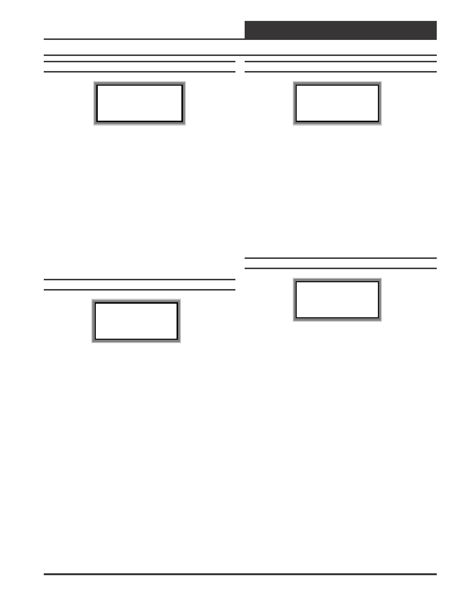
Status Screen 5
VCM v1.00 ID 59
H/C Demand: xx.x
°
F
Space Tmp.: xx.x
°
F
Line 2
Current Heating or Cooling Demand
Based on the comparison between the current HVAC Mode
Enable Temperature and the HVAC Mode Heating or
Cooling Setpoint Temperatures. This number is calculated
by subtracting the HVAC Mode Enable Temperature from
either the HVAC Mode Enable Heating Or HVAC Mode
Enable Cooling Setpoint values (depending on which Mode
is currently active ) to arrive at this value. A positive
number indicates a Cooling demand and a negative number
indicates a Heating demand.
Line 3
Current Space Temperature reading.
If you are using a Space Temperature Sensor, this line will
display the current Space Temperature during the Occupied
or Unoccupied Mode.
Line 4
Blank
S
S
S
S
Status Screen 6
VCM v1.00 ID 59
Outdoor Tmp.: xx.x
°
F
Outdoor RH..: xx.x%
Coil Tmp....: xx.x
°
F
Line 2
Current Outdoor Air Temperature.
If an Outdoor Air Temperature Sensor has been installed
and configured on the unit or an Outdoor Air Broadcast is
configured on anther VCM controller on the system, the
Outdoor Air Temperature will appear on this line. If not this
line will display a temperature that is halfway between the
Cooling and Heating Lockout Setpoints.
Line 3
Current Outdoor Air Relative Humidity
If an Outdoor Humidity Sensor has been installed and
configured on the VCM, the Outdoor Air Relative
Humidity Percentage will appear on this line. If not this
line will display 0%.
Line 4
Current Calculated Evaporator Coil Temperature
If the Suction Pressure Transducer has been installed and
configured on the unit, the calculated Evaporator Coil
Temperature will appear on this line. If not this line will
display 0°F.
S
S
S
S
Status Screen 7
VCM v1.00 ID 59
OA Dewpoint.: xx.x
°
F
Dewpoint Spt: xx.x
°
F
Line 2
Current Calculated Outdoor Air Dewpoint
Temperature
If both an Outdoor Humidity Sensor and a Outdoor Air
Temperature Sensor have been installed and configured on
the unit, the calculated Outdoor Air Dewpoint Temperature
will appear on this line. If not, this screen display 0°F.
.
Line 3
Current Outdoor Air Dewpoint Setpoint
The user adjustable Outdoor Air Dewpoint
Temperature Setpoint will appear on this line.
Line 4
Blank
S
S
S
S
Status Screen 8
VCM v1.00 ID 59
Indoor RH....: XXX%
Indoor RH Spt: XXX%
Line 2
Current Indoor Relative Humidity Percentage
If an Indoor Humidity Sensor has been installed and
configured on the unit, the current Indoor Air Relative
Humidity Percentage will appear on this line. The installed
Indoor Humidity Sensor can be either a Wall Mounted type
or a Return Air Mounted type. If an Indoor Humidity
Sensor is not installed this line will display 0%.
Line 3
Current Indoor Relative Humidity Setpoint Percentage
This is the adjustable Indoor Air Relative Humidity
Setpoint Percentage that has been set by the user.
Line 4
Blank