Orion System VCM User Manual
Page 17
Operator Interfaces
Technical Guide
17
Configuration Screens
In order to correctly setup the VCM controller you must first configure
several parameters in regard to the type of HVAC unit and system you
have installed. Most of these values and operating parameters are only
set once, at the initial system setup and are never changed.
System Manager Instructions
From any menu screen press the “Setpoint” key. The unit selection screen
will appear requesting that you enter the unit ID number. Enter the cor-
rect unit ID number of the VCM controller you want to configure and
hit the “Enter” key. You will see the screen shown below.
1)Change Setpoint
2)Configure Unit
3)Damper Force
ESC) Exit Menu
Press “2” on the keypad to enter Configuration Screen #1.
Modular Service Tool Instructions
From any menu screen press the “Configuration” key. The unit selec-
tion screen will appear requesting that you enter the unit ID number.
Enter the correct unit ID number of the VCM controller you want to
configure and hit the “Enter” key. You will then see unit configuration
screen #1.
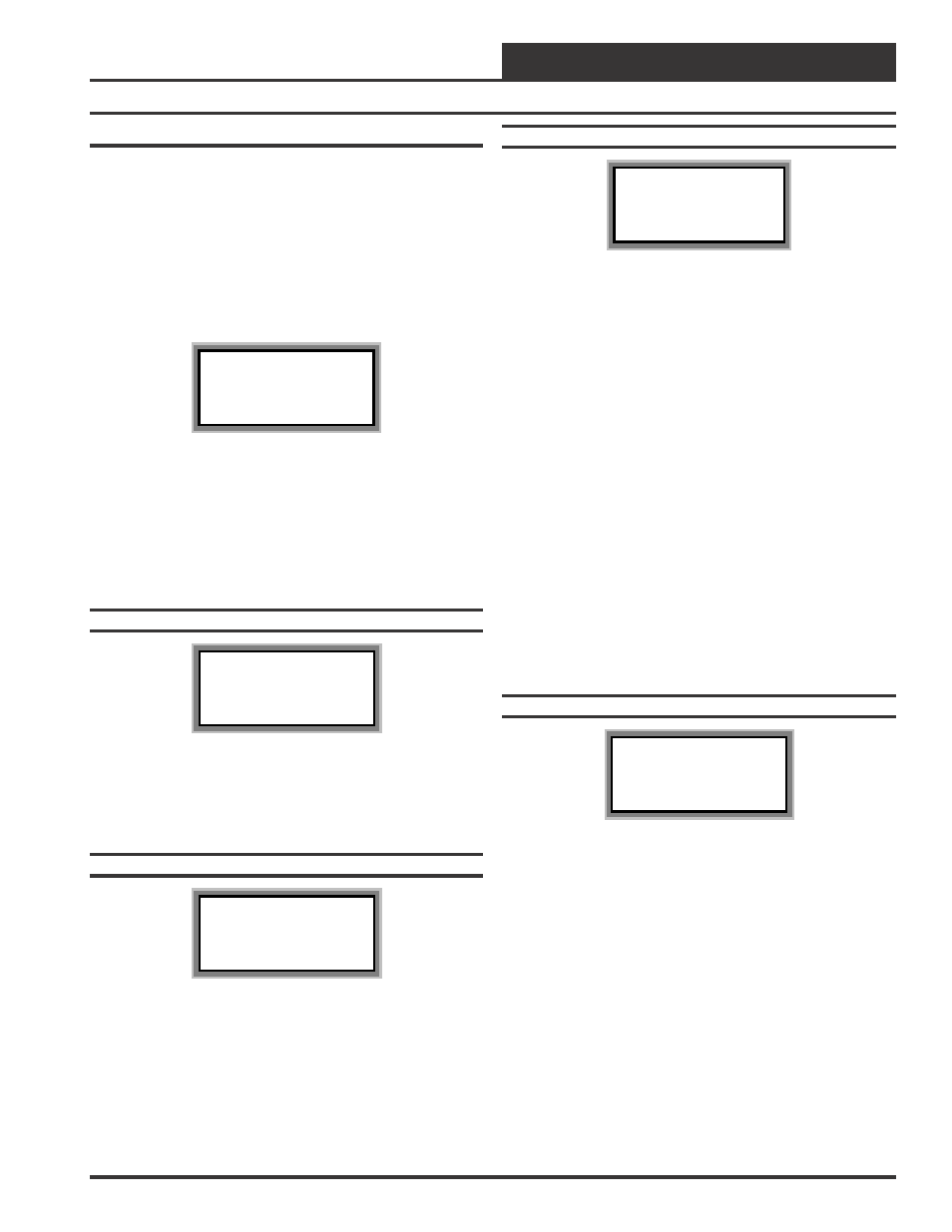
Configuration Screen #1
VCM Cnfg ID 59
Duct Static Pressure
Control: YES
[0=YES 1=NO]
If the HVAC unit has a Supply Fan that delivers a Constant Volume of
air, enter “1” for “NO”. If the HVAC unit has a Supply Fan that deliv-
ers a Variable Volume of Air using a VFD or a Bypass Damper, enter
“0” for “YES”.
Configuration Screen #2
VCM Cnfg ID 59
Supply Fan Cycle
Mode: NO
[0=NO 1=YES]
If you want the HVAC unit’s Supply Fan to run during Heating, Cool-
ing or Dehumidification Modes, enter “1” for “YES”. If you want the
HVAC unit’s Supply Fan to run continuously while in the Occupied
Mode, regardless of the Heating, Cooling or Dehumidification Modes,
enter “0” for “NO”.
Configuration Screen #3
VCM Cnfg ID 59
HVAC Mode Enable
Supply Air
Press”0” to Change
Press the “0” key to select the Temperature Sensor that will determine
the Heating, Cooling or Vent Modes of operation. The available selec-
tions are:
•••••
Supply Air
This is typical for VAV applications. Occupied Cooling
with Morning Warm-up.
•••••
Outdoor Air
This is for 100% Outdoor Air (MUA) units.
Dehumidification utilizing a Dewpoint Calculation if
equipped with an Outdoor Air Humidity sensor.
•••••
Space Temperature
This is for any unit that conditions a space and is not 100%
Outdoor air. Occupied/Unoccupied Heating, Cooling and
Vent Modes of operation.
•••••
Return Air
This selection can be used when an Average Building
Temperature (the Return Air Temperature) needs to
determine Heating, Cooling and Vent Modes of operation.
Configuration Screen #4
VCM Cnfg ID 59
HVAC Reset Source
No Reset
Press “0” to Change
Press the “0” key to select the desired Reset Source for Supply Air
Temperature Reset. The selections are Space Temperature Sensor, Re-
turn Air Temperature Sensor, Fan VFD Signal, Remote Reset Input and
No Reset. If No Reset Source is selected, the Supply Air Setpoint will
not be Reset. The Reset Source Setpoints will then become the Supply
Air Heating and Cooling Setpoints. If the Remote Reset Input is se-
lected, then the Reset Source will be the Supply Air Temperature
Setpoints when the Remote Input is not active. When the Remote Input
is active, the new Supply Air Temperature Setpoints will be the Remote
Reset Setpoints that are on Setpoint Screen #5.