Operator interfaces technical guide 43 setpoints – Orion System VCM User Manual
Page 43
Operator Interfaces
Technical Guide
43
Setpoints
Setpoint Screen #1
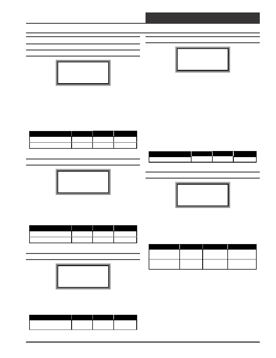
HC Box Spts IDxxxx
Occupied Setpoints
Cooling......: xx
°
F
Heating......: xx
°
F
Enter the Occupied Cooling Setpoint as the maximum temperature
you would like the zone to reach before modulating the damper open
to bring in more cold air to cool the space. Enter the Occupied Heat-
ing Setpoint as the minimum temperature you would like the zone to
reach before activating the Reheat Stages on the optional Expansion
Relay board. If this is a Cooling Only box that doesn’t contain reheat,
this setpoint will be ignored.
Description
Minimum
Default
Maximum
Cooling Spt
50
°
F
74
°
F
90
°
F
Heating Spt
50
°
F
70
°
F
90
°
F
Setpoint Screen #2
HC Box Spts IDxxxx
Unoccupied Setbacks
Cooling SetUp: xx
°
F
Heating SetBk: xx
°
F
During unoccupied hours, the Occupied Cooling Setpoint is adjusted
up by the amount entered for the Cooling SetUp. The Occupied Heat-
ing Setpoint is adjusted down by the amount entered for the Heating
SetBk.
Description
Minimum
Default
Maximum
Cooling SetUp
0
°
F
+10
°
F
+30
°
F
Heating SetBk
0
°
F
-10
°
F
-30
°
F
Setpoint Screen #3
HC Box Spts IDxxxx
AHU Heat Call
Space Temp...: xx
°
F
This setpoint allows the user to set a Space Temperature that will cause
the Box Controller to send a call for heat to the HVAC unit.
Description
Minimum
Default
Maximum
AHU Heat Call Space
Temperature
50
°
F
70
°
F
90
°
F
Setpoint Screen #4
HC Box Spts IDxxxx
Damper/Airflow Spt
Integral [Ki]..: xxx
The Box Controller normally opens it’s damper based on a Proportional
Error from Setpoint. That means if the zone temperature is 4°F from
setpoint, the damper would be 100% open or it would be modulating to
provide the Maximum CFM on Pressure Independent boxes. If the er-
ror is less than 4°F, the damper may stagnate at that position and never
satisfy the zone. If you add Integral into the damper calculation pro-
cess, this will cause the damper or airflow calculations to continue to
increase as long as the zone temperature is still above the setpoint. That
means it can provide 100% or Maximum CFM before the 4°F error is
achieved, bringing the zone under control faster than it normally would.
Start with a small ( 5 or 10 ) value, if you use this, and monitor the effect
it has. If you enter too large a value, you can create “hunting” situations
that can cause the damper actuator to prematurely wear out.
Description
Minimum
Default
Maximum
Integral
0
0
100
Setpoint Screen #5
HC Box Spts IDxxxx
Damper/Airflow Spt
Maximum..: xxx %
Vent Min.: xxx %
The Box Controller will not allow the damper or airflow calculation to
exceed the Maximum setpoint while it is allowing the damper to modu-
late. During Vent mode when there is no heating or cooling demand, the
damper or airflow will maintain at least the Vent Min amount of airflow
into the zone for ventilation.
Description
Minimum
Default
Maximum
Maximum
0% or
0 CFM
100% or
1000 CFM
100% or
30000 CFM
Vent Min.
0% or
0 CFM
25% or
250 CFM
100% or
30000 CFM