Programming the vcm controller, Technical guide operator interfaces 24 – Orion System VCM User Manual
Page 24
Technical Guide
Operator Interfaces
24
Programming The VCM Controller
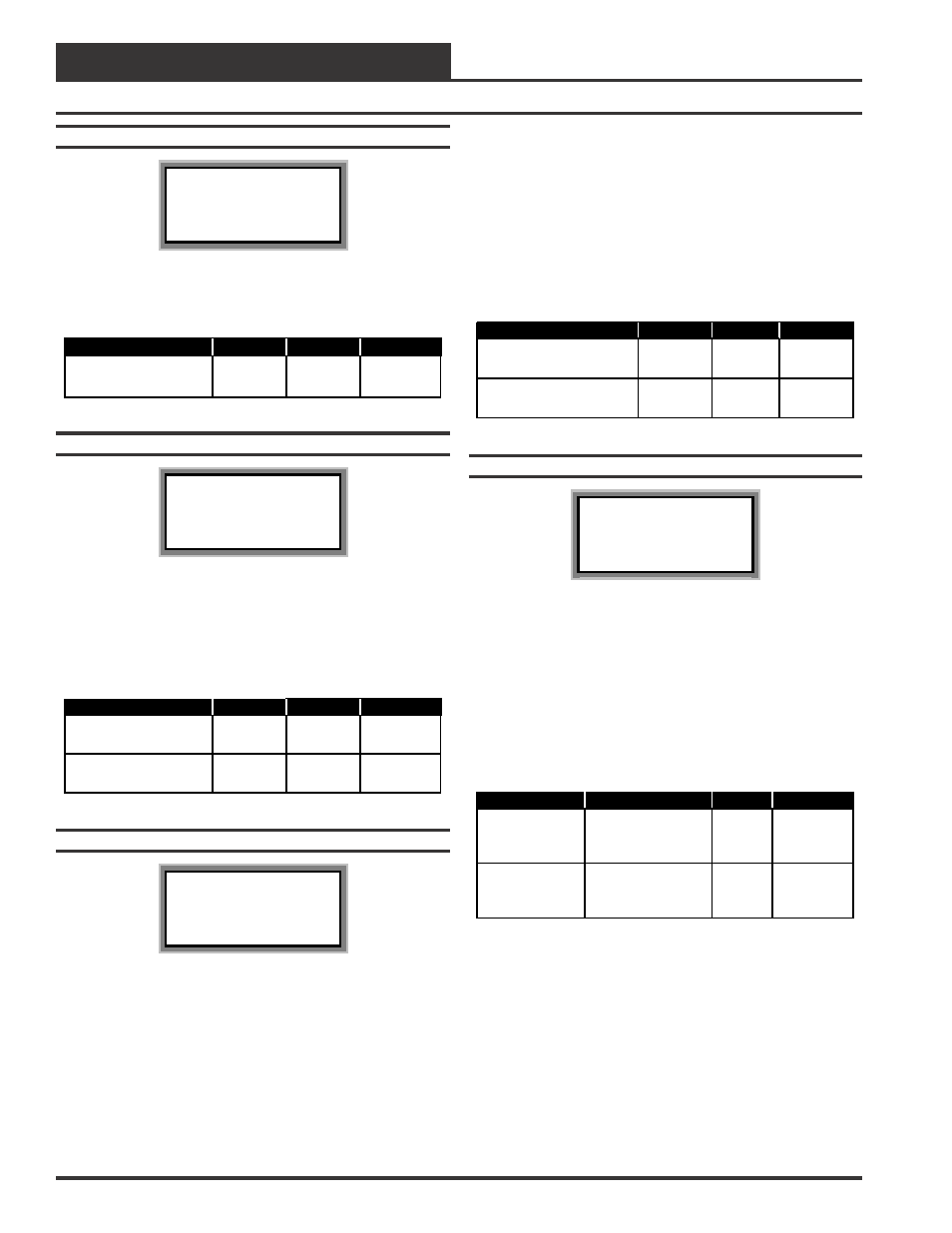
Setpoint Screen #2
VCM Spts ID 59
HVAC Mode Select
Deadband: 1.0
°
F
This Setpoint is added to and subtracted from the HVAC Mode Setpoints.
It provides the user with flexibility on when the Heating and Cooling
Modes should be active above or below the HVAC Mode Setpoints.
Description
Minimum
Default
Maximum
HVAC Mode Select
Deadband
0
°
F
1
°
F
10
°
F
Setpoint Screen #3
VCM Spts ID 59
Unoccupied Setbacks
Cooling: 5
°
F
Heating: 5
°
F
During the Unoccupied Mode of Operation, these Setpoints spread the
HVAC Mode Setpoints out by a user adjustable amount. Use only posi-
tive numbers for these Setpoints. If you do not want Cooling or Heating
to operate during the Unoccupied Mode, use the default setting of 30°F
for these setpoints.
Description
Minimum
Default
Maximum
Unoccupied Setbacks
Cooling
0
°
F
30
°
F
30
°
F
Unoccupied Setbacks
Heating
0
°
F
30
°
F
30
°
F
Setpoint Screen #4
VCM Spts ID 59
SAT/Reset Source
Cooling Spt: 75
°
F
Heating Spt: 70
°
F
If no reset source has been configured, then these setpoints will be the
Supply Air Temperature Cooling and Heating Setpoints. If the Space
or Return Air Temperature Sensor is configured as the Reset Source,
then these setpoints will be the desired temperature to be maintained
for the Reset Source. The Supply Air Temperature will automatically
be reset, warmer or colder to maintain the Cooling and Heating
Setpoints for the Reset Source. If Remote SAT Reset is configured as
the Reset Source, then these setpoints will be used for the Supply Air
Temperature Setpoints when the Remote Reset Signal is not active. If
Fan VFD Signal is configured as the Reset Source, then the Cooling
Setpoint will be the lowest Supply Air Temperature Setpoint for Cool-
ing when the Supply Fan VFD Signal is at 100%. If the Supply Fan
VFD Signal is configured as the Reset source, then the Heating Setpoint
will be the lowest Supply Air Temperature Setpoint for Heating when
the Supply Fan VFD Signal is at 0%. See Setpoint Screen #5 for more
information on the Supply Fan VFD Signal and Remote SAT Reset
setup.
Description
Minimum
Default
Maximum
Reset Source Setpnts
Cooling
30
°
F
55
°
F
80
°
F
Reset Source Setpnts
Heating
50
°
F
120
°
F
200
°
F
Setpoint Screen #5
VCM Spts ID 59
Remote SAT Reset
Cooling Spt: 65
°
F
Heating Spt: 120
°
F
When Remote SAT Reset is configured as the Reset Source, then these
setpoints will be the Supply Air Temperature Cooling and Heating
Setpoints when the Remote Reset Input is active. If the Supply Fan
VFD Signal is configured as the Reset Source, then the Cooling Setpoint
will be the highest Supply Air Temperature Setpoint for Cooling when
the Supply Fan VFD Signal is at 0%. If the Supply Fan VFD Signal is
configured as the Reset Source, then the Heating Setpoint will be the
highest Supply Air Temperature Setpoint for Heating when the Supply
Fan VFD signal is at 100%. See Setpoint Screen #4 for more informa-
tion on the Supply Fan VFD signal and Remote SAT Reset setup.
Description
Minimum
Default
Maximum
Remote SAT
Reset Cooling
Spt
Reset Source
Setpnts Cooling
55
°
F
200
°
F
Remote SAT
Reset Heating
Spt
Reset Source
Setpnts Heating
120
°
F
200
°
F