V.35 configuration, Figur ea-1 – Verilink AS56/56Plus (896-502588-001) Product Manual User Manual
Page 118
Standard Cabling for User Ports
A-4
AS56
and
AS56
Plus
User Manual
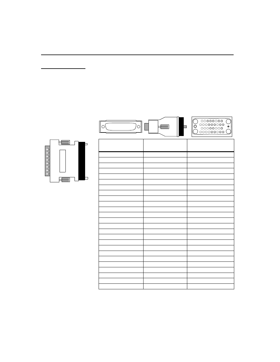
V.35 Configuration
V.35 signaling is provided through a female DB-25 connector per the
V.35 specification. With an external module, the same signals are
provided through a female M-series, 34-pin connector. The tables that
follow show the pin numbering and the pin assignments of the adapter
module included with the product.
Figure A-1
V.35 Adapter Module Pin Assignments
DB-25
(Male)
Signal
34-Pin Winchester
(Female)
1
Shield
A
2
TXD out A
P
3
RXD in A
R
4
RTS out
C
5
CTS in
D
6
DSR in
E
7
Signal Ground
B
8
DCD in
F
9
RXC in B
X
10
-
-
11
EXT CLK out B
W
12
TXC in B
a
*
* On AMP connectors, this pin is designated as “AA.”
13
-
-
14
TXD out B
S
15
TXC in A
Y
16
RXD in B
T
17
RXC in A
V
18
-
-
19
-
-
20
DTR out
H
21
-
-
22
-
-
23
-
-
24
EXT CLK out A
U
25
-
-
. . . . . . . . . . . . .
. . . . . . . . . . . .