Rs-232 configuration, Figur ea-2 – Verilink AS56/56Plus (896-502588-001) Product Manual User Manual
Page 120
Standard Cabling for User Ports
A-6
AS56
and
AS56
Plus
User Manual
Figure A-2
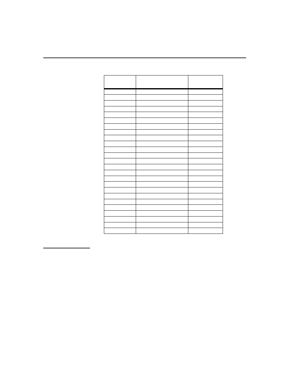
RS-530/RS-422A Pin Assignments
RS-232
Configuration
When the Access Syst em56 Serial Port is set for RS-232, the port
operates in compliance with the TIA/EIA RS-232 standards. The tables
that follow show the pin numbering and the pin assignments of the
adapter cables. The following cabling is recommended:
CBE-021-0053
0
DB-25 male connector DB-25 female connector
Crossover. Fifteen feet long. Optional at extra cost.
Signal
RS530
DB-25
RS449
DB-37
Shield
1
-
TXD out A out
2
4
RXD in A
3
6
RTS out A
4
7
CTS in A
5
9
DSR in A
6
11
Signal Ground
7
19
DCD in A
8
13
RXC in B
9
26
DCD in B
10
31
EXT CLK out B
11
35
TXC in B
12
23
CTS in B
13
27
TXD out B
14
22
TXC in A
15
5
RXD in B
16
24
RXC in A
17
8
-
18
-
RTS out B
19
25
DTR out A
20
12
-
21
-
DSR in B
22
29
DTR out B
23
30
EXT CLK out A
24
17
-
25
-