Cables for external timing, V.35 serial port cabling, Figur eb-1 – Verilink AS56/56Plus (896-502588-001) Product Manual User Manual
Page 126
Special Serial Port Cabling
B-2
AS56
and
AS56
Plus
User Manual
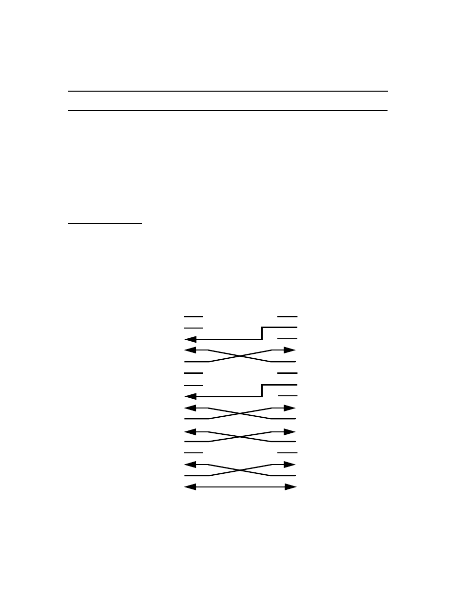
Cables for External Timing
The figures in this section describe the crossover cabling necessary to
support a V.35 and an RS-422A Serial Port #1 with External timing. Note
that the cables are not symmetrical.
The Access System 56 units have female connectors and, therefore, the
cable connectors are always male at the Access System 56 end. They will
also be male at the customer end unless specified otherwise.
V.35 Serial Port
Cabling
458-501776-
0
1
5
V.35 cross-over cable. M-series, 34-pin male
connectors at both ends. Fifteen feet long. Optional at extra cost.
Figure B-1
V.35 Serial Port #1 Cabling for External Timing
Access System 56
V.35 Serial Port
Pin Assignments
Customer V.35 DCE
Pin Assignments
M-Series,
34-pin
Signal
Signal
M-Series,
34-pin
Y
TXC-A
TXC-A
Y
V
RXC-A
RXC-A
V
U
Ext. TXC-A
Ext. TXC-A
U
P
TXD-A
TXD-A
P
AA (a)
RXD-A
RXD-A
R
R
TXC-B
TXC-B
AA (a)
X
RXC-B
RXC-B
X
W
Ext. TXC-B
Ext. TXC-B
W
S
TXD-B
TXD-B
S
T
RXD-B
RXD-B
T
C
RTS
RTS
C
F
DCD
DCD
F
D
CTS
CTS
D
H
DTR
DTR
H
E
DSR
DSR
E
B
GROUND
GROUND
B
x
x
x
x
x
x
x
x
x
x