Switching ranges, Switching inputs and outputs – HEIDENHAIN ND 920 User Manual
Page 62
62
High signal: U
amin
= U
s
– 1.6 V
I
amax
= 100 mA
Voltage spikes up to 36 V for t < 100 ms are
permissible.
Inductive loads must be driven with a quenching
diode parallel to the inductance.
Up to eight switching ranges can be defined with operating parameters.
You can assign the switching ranges to the axes as desired with
parameters P60 and P61. The switching ranges are symmetrical to the
display value 0.
The switching signals are present on the D-sub connection X41 on pins
14 to 21.
Pins 23 to 25 must be connected to 24 Vdc (U
s
). Outside the switching
ranges the 24 Vdc circuit to the switching outputs at pins 14 to 21 is
closed; within the switching ranges it is open.
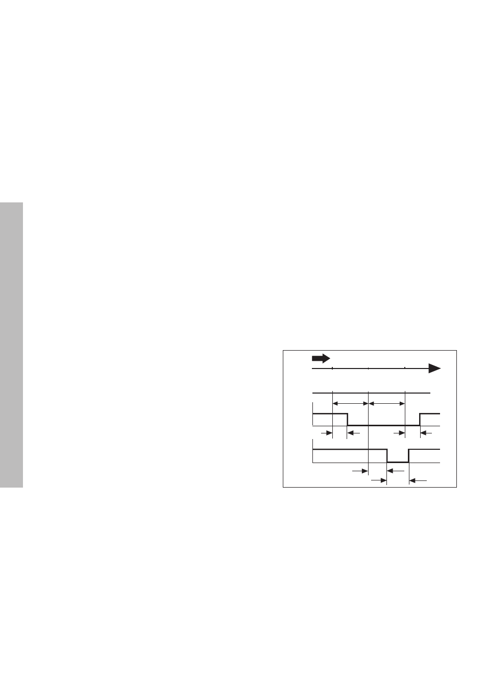
The diagram at right shows the voltage curves U
A1
and U
A2
of outputs
A1 and A2 when approaching zero from the negative direction and
when the switching points P1 and P2 are assigned to the X axis.
DC supply voltage
U
s
= +24 Vdc
U
smin
= +20.4 Vdc
U
smax
= +31.0 Vdc
Switching ranges
Permissible loading of the outputs
Ð10 0 +10
X
t
t
U
A1
U
A2
P1 P2 (P1')
max. max.
80ms 80ms
max.
min.
24V
24V
180ms
80ms
10
10
Switching Inputs and Outputs